Krell Industries CIPHER, Owner Reference Manual
The Krell Industries CIPHER, a cutting-edge device, revolutionizes entertainment systems. Unlock its full potential with the Owner Reference Manual, available for free download on our website. Discover step-by-step instructions, troubleshooting tips, and expert advice to maximize your audiovisual experience. Download the manual now at manualshive.com.
Share
Download


Reviews:
No comments
Related manuals for CIPHER
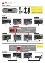
M50
Brand: NAD Pages: 2

SP80
Brand: Youtopia Pages: 24

MDC-2F4
Brand: PROEM Pages: 9

MP 3100 HV
Brand: T+A Pages: 74

X-355
Brand: Akai Pages: 28

PDV-708U
Brand: Durabrand Pages: 28

DX-C300
Brand: Onkyo Pages: 15

BS-251
Brand: Vivax Pages: 56

HD Base 3.0
Brand: DUNE Pages: 48

NMP-200 - Network Media Player Ess-based Processor
Brand: ViewSonic Pages: 2

0015
Brand: Oliver Pages: 23

Prodigy 4K
Brand: Xtreamer Pages: 2

Xemio-241
Brand: LENCO Pages: 51

DMP210N
Brand: Hitachi Pages: 17

DMP2
Brand: Hitachi Pages: 35

DMP270E
Brand: Hitachi Pages: 20

DVP1080HD
Brand: Faroudja Pages: 22

DMP470E
Brand: Hitachi Pages: 11


