background image

RT10116

Version 20070701

·   Woodworking machines are dangerous, and can cause personal injury if not
 used 

properly.

·   Read safety instructions and operating instructions for your machine completely, 
  before using products.  Using this system before understanding its safe and
  proper use could result in serious injury to the operator.  

·   Failure to follow these rules may result in serious personal injury.

·   For your own safety, read instruction manual before operating the tool.  Learn the 
  tools application and limitations as well as the specifi c hazards distinctive to it.

·   Keep all guards and safety devices in proper place while using these products. 

·   Always wear safety glasses.

·   Keep hands well away from the rotating bit when operating machine.

·   Avoid akward hand positions, where a sudden slip could cause contact with the 
  rotating bit.  

·   This system was designed for certain applications only.  Kreg strongly recommends 
  that this system NOT be modifi ed and/or used for any application other than 
  for which it was designed.  If you have any questions relative to its application, 
  DO NOT use the tool until you have written, phoned, or e-mailed Kreg Tool and 
  have been advised accordingly.

·   Be aware of kickbacks.  Kickbacks occur when the workpiece binds-up while being 
  routed, causing it to twist, jump, and possibly become airborne.  To avoid kick
  backs (and potential injury) always use sharp bits, keep the machine aligned and  
  maintained properly, and adequately secure/support the workpiece.

·   Turn machine off before adjusting.  Never adjust the fence, plate level, reducing rings, 
  or any other part of the tool while the machine is running.

·   Wait for the machine to stop.  Make sure the router comes to a complete stop before 
  adjusting the workpiece or workpiece-angle.

·   Ground electric machines.  If your machine is equipped with a three-prong plug, it
  should be plugged into a three-hole electrical receptacle only.  If the proper
  outlet is not available, have one installed by a qualifi ed electrician before use. 
  Never remove the third prong, and never modify the provided plug in any way.  

·   Don’t operate in a dangerous or unclean environment.  Don’t use power tools in
  damp or wet locations, or expose them to rain.  Keep work area well-lit,
  un-cluttered, and clean.

·   Keep children and visitors away.  All children and visitors should be kept a safe distance 
  from the work area, and should not operate the tool under any condition.

·   Make your workshop “child-proof”.  Use padlocks, master switches, or any other means 
  necessary to make your work area safe for children.  

·   Use the right tool.  Never ‘force’ the tool to do work for which it was not intended.  If used 
  properly, the tool will produce better results in less time, under safer conditions.

·   Wear proper apparel.  No loose clothing, gloves, neckties, rings, bracelets, or any other 
  jewelry that could possibly get caught in moving parts.  Non-slip footwear is highly 
  recommended, as is protective hair covering.  Remember to always use safety glasses, 
 specifi cally designed as safety wear.  

·   Secure the workpiece.  Use clamps or a vise to hold work when it is practical and safe.   
  Using the proper tool may allow you to free both hands for tool operation.  Also, be sure 
  to never overreach.  

·   Secure your tools.  In the event of the machine tipping or sliding, it is always    
  recommended to secure your tools to the machine during use.    

·   Keep the proper footing and balance.  Ensure that you are in no danger of slipping or 
  sliding once you turn the machine on.  Once again, non-slip footwear is highly 
 recommended.

·   Maintain tools in top condition.  Keep tools sharp, clean, and properly maintained for the 
  highest quality and safest performance.  Remember to properly follow all lubrication and 
  accessory maintenance practices, as detailed in this Instruction Manual.

·   Disconnect tool before servicing.  When changing accessories such as bits, clamps, etc., 
  making any sort of physical assessment of the tool, or when motor is being mounted/
  connected, remember to disconnect the machine from its power source.  This will reduce 
  the possibility of accidentally engaging the machine.

·   Check for damaged parts.  Before use of the tool, a careful assessment of all guards and  
  other parts should be made to ensure that it will operate properly,  and perform as 
  intended.  Check for alignment of moving parts, binding of moving parts, breakage of 
  parts, mounting, and any other conditions that may affect its operation.  A guard or other 
  part that is damaged should be properly repaired or replaced as soon as possible, 
  preceding any additional use.  Do not use the tool if you are not qualifi ed to make these 
  sorts of assessments.

·   Never leave a running machine unattended.  Always turn the machine’s power “OFF” 
  after operation.  Do not leave the tool until it comes to a complete stop.

·   Drugs, alcohol, medication warning.  Do not operate tool while under the infl uence of 
  drugs, alcohol, or any medications.
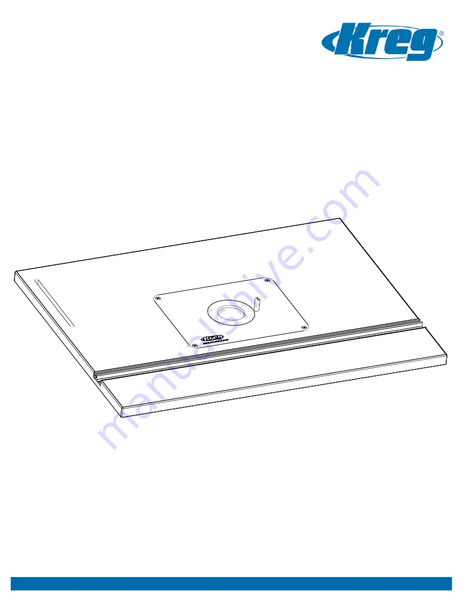
Router Table Top

Precision 

ASSEMBLY INSTRUCTIONS

Item# PRS1020

Other Precision Routing Products

Safety Guidelines

7.

(

24” x 32”

)

 Tools Required:

• 5/64” Allen Wrench
• Phillips Head Screwdriver
• Flat Head Screwdriver
• 6” #2 Square Driver
• 1/8” Allen Wrench (Included)
• 3” #2 Square Driver (Included)

www.kregtool.com • 800.447.8638

This unique featherboard can be quickly and easily connected to almost any 
miter slot or t-slot without the need for additional hardware.  It features a durable 
plastic composite body which ensures optimum workpiece pressure. 

True-FLEX

True-FLEX

Featherboard

Featherboard

TM

Item# PRS3010

Taking cues from high-end table saw rip fences, this groundbreaking router 
fence provides an entirely new way to work. It’ll make every project you 
start faster, easier, and far more precise than ever before.

Precision Router Table Fence

Precision Router Table Fence

Item# PRS1010

www.kregtool.com • 800.447.8638

Come meet the entire family of Precision Routing Products 

Come meet the entire family of Precision Routing Products 

at www.kregtool.com

at www.kregtool.com

Summary of Contents for PRS1020

Page 1: ...Top Precision ASSEMBLY INSTRUCTIONS Item PRS1020 24 x 32 Tools Required 5 64 Allen Wrench Phillips Head Screwdriver Flat Head Screwdriver 6 2 Square Driver 1 8 Allen Wrench Included 3 2 Square Driver Included www kregtool com 800 447 8638 ...

Page 2: ... the four rails with the pre drilled holes on the bottom side of the Table Top The Kreg logo located on the front of the stand should be located on the same side and parallel to the T Miter Track opening on the Router Table Top Once the table is positioned correctly use a 6 2 Square driver bit and twelve Coarse Screws included with the Universal Steel Stand to secure the two together being careful...

Page 3: ...PORTANT When positioning your base plate for drilling make sure that none of the holes you are about to drill line up over the pre drilled Start Pin Hole in the insert plate Once you have the base plate from your router aligned where you want it on the template use heavy duty masking tape to secure your base plate to the bull s eye template Tape on at least four sides of your base plate to ensure ...

Page 4: ... Set Screw DK1522 1 10 1 4 20 x 1 1 2 Set Screw RT10111 8 11 1 1 4 Coarse Screw SML C125 12 12 1 4 20 x 1 3 4 Flat Head MS RT10112 4 13 8 32 x 1 4 Set Screw RT10110 6 14 8 32 x 5 16 Flat Head MS RT10109 3 15 10 32 x 3 4 Flat Head MS DK1547 3 16 3 4 Coarse Screw RT10192 8 Hardware Item Description Part Quantity 2 Precision Router Table Top Exploded Parts Diagram 3 4 A B C D E F G H A H G F E D C B ...

Page 5: ...the reducing ring and hold it securely in place Note We recommend adjusting both reducing rings at this time This will save time later as you change which reducing ring you want to use and also reduces the possibility of losing the second set of small Flat Point Socket Set Screws After you have leveled one reducing ring remove it and level the other Insert three 8 32 x Flat Point Socket Set Screws...

Page 6: ...ly be used with router bits that have a bearing Start with your work piece touching the starter pin but not in contact with the router bit Ease the material into the cutter and make contact with the ball bearing on the bit 6 In Use Starting Pin Once you ve made solid contact with the ball bearing you can ease off of the starting pin and allow the work piece to glide along the bit s bearing ...

Page 7: ...e clothing gloves neckties rings bracelets or any other jewelry that could possibly get caught in moving parts Non slip footwear is highly recommended as is protective hair covering Remember to always use safety glasses specifically designed as safety wear Secure the workpiece Use clamps or a vise to hold work when it is practical and safe Using the proper tool may allow you to free both hands for...

Page 8: ...Tools Required 7 16 Open Ended Wrench Flat Head Screwdriver Phillips Head Screwdriver RouterTableFence Precision ASSEMBLY INSTRUCTIONS Item PRS1010 RT10142 Version 20070701 www kregtool com 800 447 8638 ...

Page 9: ...the workpiece or workpiece angle Ground electric machines If your machine is equipped with a three prong plug it should be plugged into a three hole electrical receptacle only If the proper outlet is not available have one installed by a qualified electrician before use Never remove the third prong and never modify the provided plug in any way Don t operate in a dangerous or unclean environment Do...

Page 10: ... play out of the fence and allows for more fluid motion of the Mounting Rail Make adjustments as necessary Step 4 Locate the Fence Mount 3 and align the four holes with the corresponding holes on the Clamp Block 2 Secure the two together using the four Brass Washers 17 and four 20 x 3 8 Phillips Pan Head Machine Screws 18 without tightening completely You will need to adjust the positioning of the...

Page 11: ...1504 12 18 1 4 20 X 3 8 PAN HEAD MS RT10137 8 19 KNURLED THUMB SCREW RT10185 1 20 10 32 X 1 4 NYLON SCREW FT4064 1 21 1 4 NYLON SNAP RIVET RT10130 8 22 1 4 20 X 1 FLAT HEAD MS RT10136 6 23 1 4 20 HEX NUT DK1510 5 24 PLASTIC SPACER WASHER RT10134 2 25 1 4 20 X 1 1 4 T BOLT FT4212 2 26 1 4 20 X 2 1 4 HEX BOLT RT10186 2 27 1 4 20 JAM NUT RT10141 5 28 1 COARSE SCREW SML C1 4 29 NYLON SET SCREW FT4102 ...

Page 12: ... T Slot Slide the slotted end of the Right Angle Bracket 12 around the Hex Bolt and fasten with one Fender Washer 33 and one Hex Nut Before tightening the nut align the Right Angle Bracket over the 6 slot on the left side of the Kreg Router Table Top Place the Brass T Nut 30 through the slot from the underside of the Router Table Top and attach the Extension Knob Asembly 13 by putting it through t...

Page 13: ... two Plastic Spacer Washers 24 onto each T Bolt and place the Fence Guard 11 on to each T Bolt Fasten using two Brass Washers 17 and two Small T Knobs 16 Slide the Precision Lens Cursor 10 into the Mounting Rail as far as is shown and lock it into place using the 10 32 x Nylon Screw 20 This Screw can be loosened and re tightened to make any adjustments necessary to the Precision Lens Cursor Slide ...

Page 14: ...ide the rods into the corresponding deeper recesses as shown in the right photo When the rods are inserted and you have the correct depth setting re tighten the fence face to the fence To position your fence for use with a common edge bearing bit start by loosening the individual fence faces and positioning them as close as possible to the cutter without making contact with the bit Rotate the bit ...

Page 15: ...at 800 447 8638 with any questions regarding the assembly of this stand www kregtool com 800 447 8638 Item KRS1030 Short Stretcher 4 Height Adjusters 4 Long Stretcher 4 Levelers 4 Parts Identification Legs 4 Hardware 5 16 Hex Flange Nuts 50 1 2 Hex Flange Nuts 8 5 16 Carriage Bolts 50 3 4 Wood Screws 20 ASSEMBLY INSTRUCTIONS NK7563A Version 20070201 ...

Page 16: ...ore Step 1 Step 2 A B C 900 A B C 900 Step 2 Final Assembly Shown Step 1 Final Assembly Shown ConstructingSideAssemblies In this step you will be joining four 4 Long Stretchers and four 4 Legs to construct two separate side assemblies Special Note One of your Long Stretchers includes a Kreg logo You may choose where you would like this stretcher to be positioned Begin by laying two 2 Legs flat on ...

Page 17: ...g Levelers In this step you will be adding the Levelers to the bottom of each Height Adjuster Rotate one flange nut onto the Leveler stud and thread it down until it is approximately one inch from the base of the leveler foot as shown in image A Then place the Leveler Stud through the opening in the bottom of the Height Adjuster as shown in image B Thread the second flange nut onto the Leveler stu...

Page 18: ...hown in image B All Kreg table top solutions come with pre drilled holes at their base which align with holes in the stand These tables tops can be attached to the Universal Steel Stand using the included screws Please reference specific table top instructions for further detail For more information on Kreg table tops visit www kregtool com A B Step 5 Final Assembly Shown Mobilize your stand Add t...

Reviews: