background image

E-1

C350

4036-7762-04

INSTALLATION MANUAL

 Applied Machine: C350

KONICA MINOLTA
BUSINESS TECHNOLOGIES, INC.

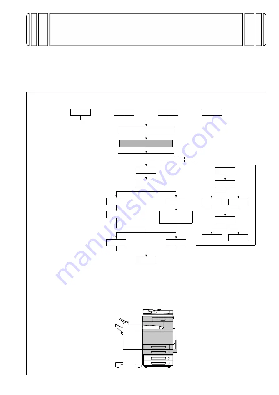
I.Outline of Installation Procedures for 4036 System

When installing the machine and associated options as a system, follow the order shown on the upper.

Caution:

• For the detailed installation procedures for each option, follow the instructions given in the corresponding

Installation Manual and perform the procedures correctly.

• Once the Power Switch is turned ON, do not turn OFF it until the installation work has been completed.
• Make available collective manpower of an appropriate size for transporting the machine. (Machine mass:

100 kg/229 lb)

 Electron System Options

PC-101

PC-201

DK-501

DF-601

AD-501

JS-601

FS-501

WT-501

FS-601

OC-501

PK-501/PK-4/

PK-131

Copier/Printer Machine

HD-501

EM-301

PC-401

Dehumidifier Heater 1C

EK-501

VI-501

VK-501

DT-105

Electron System Options

MC-501

IC-401

< Important >
Be sure to correctly follow the procedures in order as explained in this
Installation Manual.
If you do not follow the procedure in order, the image trouble may occur. 

Summary of Contents for bizhub C350

Page 1: ...ce the Power Switch is turned ON do not turn OFF it until the installation work has been completed Make available collective manpower of an appropriate size for transporting the machine Machine mass 100 kg 229 lb Electron System Options PC 101 PC 201 DK 501 DF 601 AD 501 JS 601 FS 501 WT 501 FS 601 OC 501 PK 501 PK 4 PK 131 Copier Printer Machine HD 501 EM 301 PC 401 Dehumidifier Heater 1C EK 501 ...

Page 2: ...No Name Q ty 1 Imaging unit IU Y M C BK 4 2 Power cord 1 3 Cord clamp 1 4 User s Guide holder 1 5 User s Guide 1 6 Enlarge Display Mode User s Guide 1 7 Creative Image Book 1 8 Quick Guide Printer Controller 1 9 Quick Guide PageScope Cabinet Pro 1 10 Installation Manual this manual 1 11 Installation Guide for Printer Controller 1 12 Warranty card 1 13 Setup report 1 14 End User Software License Ag...

Page 3: ... tape from different parts of the machine 2 Remove the packing bracket 3 Remove the protective sheet 4 Slide out the 1st drawer and remove protective tape and packing materials from the inside of the drawer 5 Slide out the 2nd drawer and remove protective tape from the inside of the drawer ...

Page 4: ...he IU in the level position insert it all the way as far as it will go Caution When inserting the IU make sure that the leading edge of the IU is aligned with the mounting posi tion label indicated on the machine Make sure that the IU is inserted all the way into the machine 5 Holding the IU indicated by the arrow in the illus tration pull out the PC Drum protective sheet Caution Pull out the PC D...

Page 5: ...to agitate toner 4 Remove the protective tape and the protective cap 5 Swing the fixing lever downward 6 Load the toner bottle in position Make sure that the gear is on the rear side 7 Swing the fixing lever upward to fix the toner bot tle in position Make sure that the fixing lever is positively swung into position 8 Using the same procedure install the toner bot tles for other colors of toner 9 ...

Page 6: ...the power cord Then secure the cord clamp using the screw that has just been removed Caution This step may not be performed depending on the applicable marketing area 4 Plug the power cord into the power outlet 5 Attach the cap A and B enclosed with the machine 6 Attach the connector cover enclosed with the machine VIII Installing the User s Guide Holder Install the user s guide holder ...

Page 7: ...a types selection dial in the Plain position XI Setting Gradation Adjust 1 Check that A3 or Ledger paper is loaded in the drawer 2 Display the Tech Rep Mode screen For details of how to display the Tech Rep Mode screen see the service manual 3 Select Gradation Adjust 4 Press the start key A test pattern will then be pro duced on the A3 or Ledger paper 5 Place the test pattern face down on the orig...

Page 8: ...ing 2 Select the item you want to set and press the clear key 3 Enter the data for the year month day and time of day from the 10 key pad 4 Touch Enter 5 Touch Exit three times 6 Display the Date Time Input screen To display the Date Time Input screen press Stop 1 1 4 4 Clear on the Control Panel Input the Service Code 7 Press the clear key 8 Enter the data for the year month day and time of day f...

Page 9: ...e procedure enter the serial numbers of all other units Caution Entering the serial number of the IR is not needed 5 Touch END XIV Unit Change Caution This function allows the user to select the type of message that will appear when the replacement time arrives for each of the different units 1 Display the Tech Rep Mode screen For details of how to display the Tech Rep Mode screen see the service ...

Page 10: ... Affixing the Drawer Labels Affix the drawer label XVII Adjusting Registration of Paper Source Options PC 101 401 1 Display the Tech Rep Mode screen For details of how to display the Tech Rep Mode screen see the service manual 2 Select the function to be used as follows Machine Adjust PRT Area Left Margin 3rd 3 Measure width A on the test pattern produced to check to see if it falls within the spe...

Page 11: ... width falls outside the specified range adjust with or key and then make the check again AD 501 9 Display the Tech Rep Mode screen For details of how to display the Tech Rep Mode screen see the service manual 10 Select the function to be used as follows Machine Adjust PRT Area Dup Left Margin 1st 11 Measure width A on the backside of the test pat tern produced to check to see if it falls within t...

Page 12: ...E 12 XVIII Installing the Drawer Cover If a paper source option is mounted install the Drawer Cover that comes with the machine using the Mounting Screws that also come with the machine ...

Reviews: