background image

TT-1618 6/14

INSTALLATION INSTRUCTIONS

Original Issue Date:

6/14

Model:

6--60 kW Generator Sets with RDC2/DC2, VSC, or RDC/DC Controller

Market:

Residential/Light Commercial

Subject:

OnCue

r

Plus Wireless Kits GM62465-KP3-QS and GM81385-KP3-QS

Introduction

The OnCue

r

Plus Wireless Kit allows wireless

connection of residential/light commercial generator

sets to the owner’s wireless router for Internet access.

Use this kit to connect the generator set to the Internet

for the Kohler

r

OnCue

r

Plus Generator Management

System.

The kit uses a wireless access point (AP) to connect the

generator set to the Internet without running a cable

from the owner’s router to the generator set. The

wireless AP is installed inside the generator enclosure

and powered by the generator’s engine starting battery.

These instructions explain installation and setup of the

wireless AP.

The VHB tape provided with the kit allows installation of

the kit components without drilling additional holes or

using special tools. The ambient temperature must be

warmer than 0

_

C (32

_

F) at the time of installation. Once

installed, the tape is rated for --35 to 110

_

C

(--31 to 230

_

F).

See Figure 1 to identify the correct OnCue Plus wireless

kit for your generator model. See Figure 2 for the

wireless access point (tape not shown).

Special Equipment

The following items are required for installation and

setup.

D

Wireless router for Internet connection, customer-

provided

D

The customer’s wireless network security properties

and password are required.

Step 11 of these

instructions explains how to obtain this information.

D

Laptop computer (for initial setup only)

D

Network cable for temporary connection of laptop PC

to the kit (for initial setup only)

Generator Model

Wireless Kit Number

14/20RES

GM62465-KP3-QS

6VSG
14/20RESA
38/48/60RCL

GM81385-KP3-QS

Figure 1

Kits and Models

5

tt1618

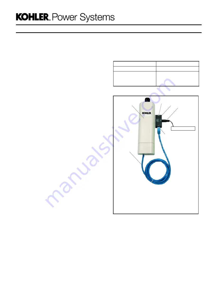
1. Wireless access point GM91273-1

2. Cable 357477

3. LAN port

4. Power over Ethernet (PoE) box GM91273-3

5. Power cable provided with kit (see Figure 4)

6. PoE port

Note:

VHB mounting tape is not shown in this photo.

4

1

2

6

See Figure 4.

3

Figure 2

GM91273 Wireless Access Point

Assembly

Summary of Contents for GM62465-KP3-QS

Page 1: ...ditional holes or using special tools The ambient temperature must be warmer than 0_C 32_F at the time of installation Once installed the tape is rated for 35 to 110_C 31 to 230_F See Figure 1 to identify the correct OnCue Plus wireless kit for your generator model See Figure 2 for the wireless access point tape not shown Special Equipment The following items are required for installation and setu...

Page 2: ...ur in a particular installation If this equipment does cause harmful interference to radio or television reception which can be identified by turning the equipmentoffand on theuser isencouraged to try to correct the interference by one of the following measures D Reorient or relocate the receiving antenna D Increase the separation between the equipment and the receiver D Connect the equipment into...

Page 3: ... the PoE box and access point will be mounted are clean and dry 3 2 Cut one piece of VHB tape approximately 1 inch long Use the tape to attach the Power over Ethernet PoE box GM91273 3 inside the enclosure as shown for your model in Figure 5 Figure 6 or Figure 7 3 3 Cut two or three pieces of the VHB tape GM91273 5 provided in the kit approximately 2 5 inches long Use the VHB tape to attach wirele...

Page 4: ...4 TT 1618 6 14 Figure 5 Wireless AP Assembly Drawing GM81385 Sheet 1 of 3 ...

Page 5: ...TT 1618 6 14 5 Figure 6 Wireless AP Assembly Drawing GM81385 Sheet 2 of 3 ...

Page 6: ...6 TT 1618 6 14 Figure 7 Wireless AP Assembly Drawing GM81385 Sheet 3 of 3 ...

Page 7: ...Macr computers go to step 6 5 1 Click on the the Windows start menu icon in the lower left corner of your screen See Figure 8 5 2 Type network connections into the Search programs and files box 5 3 Press Enter or click on View network connections 5 4 Click on Local Area Connection Figure 8 Selecting the Local Area Network Connection 5 5 Select Internet Protocol Version 4 See Figure 9 5 6 Click Pro...

Page 8: ...re 11 7 3 Press Enter The window shown in Figure 12 opens Figure 11 Enter Gateway Address in Internet Explorer 8 Sign into the wireless access point 8 1 Enter admin for Name 8 2 Enter password for Password 8 3 Press Login password Figure 12 Signing in to the Access Point 9 Configure the wireless access point 9 1 Click the System tab See Figure 13 9 2 Under Basic Settings change Network Mode to Bri...

Page 9: ...n this document See Figure 16 10 2 Click the Apply button to save the settings Note The name of the customer s wireless network appears here Figure 16 Select the Customer s Wireless Network 11 Connect to the customer s wireless network 11 1 Clickon the networkicon in the lower rightcorner of the screen See Figure 17 11 2 Click on the customer s wireless network shown here as Customer_Wireless 11 3...

Page 10: ...ow characters to see the required security settings for the wireless access point See Figure 19 Note PSK Personal Figure 19 Security Settings 13 Enter the wireless profile settings 13 1 Click on the Wireless tab 13 2 Under Profile Settings Wireless Network Name should be the customer s wireless 13 3 Fill in Security Settings from step 12 13 3 1 Network Authentication Note PSK Personal 13 3 2 Data ...

Page 11: ...3 Press Enter or click on View network connections Figure 21 Search for Network Connections 14 4 Click on the Local Area Connection See Figure 22 Figure 22 Select Local Area Connection 14 5 Select Internet Protocol Version 4 See Figure 23 14 6 Click on Properties Figure 23 Select Internet Protocol Version 4 14 7 Select Obtain an IP address automatically See Figure 24 14 8 Click OK 14 9 Go to step ...

Page 12: ...ection 16 4 Disconnect the laptop from the wireless access point Figure 25 Disconnect from Wireless 17 Connect the LAN port on the PoE box to the generator set s network cable A network cable is provided on the generator set and factory connected to the generator controller See Figure 5 Figure 6 or Figure 7 for the PoE box and network cable locations on the generator See Figure 2 for the location ...

Page 13: ...he customer s wireless network to find the default gateway IP address The procedure varies for different operating systems search the Internet for finding default gateway IP address via a personal computer to find instructions Ping Interval and Failure Count The OnCue Plus server is set to notify a customer if a device has lost connection for 1 hour or more The ping interval multiplied by the fail...

Page 14: ...hdog settings as described below 21 1 Set the Ping Interval to 300 seconds 21 2 Set the Failure Count to Reboot to 9 21 3 Click Apply 21 4 Follow steps 16 through 18 to disconnect the laptop and return the system to service Device Reset Button Note Do not press the reset button on the wireless access point Pressing the reset button will change the IP address of the access point to 192 168 1 1 and ...

Page 15: ... On WLAN Enabled Blinking WLAN Activity WLAN Client Mode Off WLAN Disabled Green Blinking Good Connection Yellow blinking Acceptable Quality Red Blinking Poor Connection Internal Antenna Electrical Specifications Antenna shape Patch array RF frequency band 2 4 2 5 GHz Power handling 2W Impedance 50 Ohms VSWR Less than 2 0 Polarization Linear vertical Antenna Gain Peak gain 2 45 GHz 8 45 dBi Vertic...

Page 16: ...ue App Quick Start Guide G18 247 1 S S WiFi Kit for RDC2 Res Coml G6 137 1 Decal OnCue Activation Code GM81386 1 Cable 3 ft RJ 45 357477 1 Kit Wireless Access Point GM91273 1 Access Point Wireless GM91273 1 1 Port Power over Ethernet GM91273 3 1 Tape VHB 3 4 10in Long GM91273 5 1 O M OnCue Plus Res Coml TP 6928 1 Install Guide WiFi Kit Res Coml TT 1618 KOHLER CO Kohler Wisconsin 53044 USA Phone 92...

Reviews: