background image

Congratulations, and welcome to the fabulous world of 
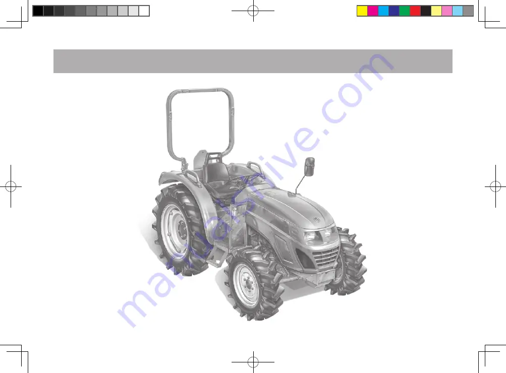
LX500L

 ownership, where serious work is made fun 

again! 

This versatile tractor is a culmination of the entire tractor and diesel knowledge gained by the Daedong Indus-

trial Co.,LTD over the years since 1947 and has been designed with the finest materials and under rigid quality 

control standards  set forth by the 

KIOTI

 Engineering Department.

Knowledge of tractor operation is essential for many years of dependable service and reliability. To help new 

owner’s familiarize themselves with the 

KIOTI LX500L

, it is the policy of 

KIOTI

 tractor to provide an owner’s 

manual which includes helpful information about tractor safety, operation and maintenance. If the information 

you seek is not found in this manual, your 

KIOTI

 tractor dealer will be happy to help you. 

Please feel free to contact 

DAEDONG IND. CO.,LTD

 with your questions/concerns. 

FOREWORD

LX500_en_om_00.indd   1

2012-11-27   오후 2:56:01

Summary of Contents for LX500L

Page 1: ...TI Engineering Department Knowledge of tractor operation is essential for many years of dependable service and reliability To help new owner s familiarize themselves with the KIOTI LX500L it is the po...

Page 2: ...sold or used outside the European Community local laws will prevail Main protections on the tractors discussed in this manual ISO 3600 EU standards DESCRIPTION NON CABIN 1 ROPS Protection against over...

Page 3: ...n harm serious injury or death to you or other persons if the warning is not heeded Follow the advice provided with the warning CAUTION This indicates that a condition may result in damage to your veh...

Page 4: ...Per Minute Hi Lo High Speed Low Speed HST Hydrostatic Transmission m s Meters Per Second PTO Power Take Off RH LH Right hand and Left hand sides are determined by facing in the direction of forward t...

Page 5: ...Travel Light Battery Charging Condition Fast L Low Speed Travel Light Engine Oil Pressure Slow Auto Draft Work Light Turn Signal Creep Auto Level Work Light Power Take Off Clutch Control On Position...

Page 6: ...LX500_en_om_00 indd 6 2012 11 27 2 54 38...

Page 7: ...SCRIPTION OF OPERATING SYSTEM OPERATION 3 POINT HITCH DRAWBAR HYDRAULIC UNIT TIRES TREAD AND BALLAST MAINTENANCE PERIODIC SERVICE STORAGE TROUBLESHOOTING INDEX SECTION TABLE OF CONTENTS 1 2 3 4 5 6 7...

Page 8: ...OF TRACTOR 2 1 SERVICING 2 2 SPECIFICATIONS 3 1 Specifications 3 2 TRAVELING SPEED 3 5 noise levels as perceived by the operator 3 7 VIBRATION LEVELS OF THE TRACTOR EXPOSITION TO VIBRATIONS 3 7 IMPLEM...

Page 9: ...LAMP 5 23 HIGH BEAM LAMP 5 23 TURN SIGNAL LAMP 5 24 GLOW PLUG INDICATOR 5 24 PARKING BRAKE LAMP 5 24 PTO INDICATOR 5 25 4WD INDICATOR 5 25 QUICK TURN INDICATOR 5 25 PARKING 5 26 HOW TO DRIVE 5 26 OPER...

Page 10: ...5 Mass es and tire s 8 6 MAINTENANCE 9 1 SERVICE INTERVALS 9 2 LUBRICANTS 9 4 PERIODIC SERVICE 10 1 HOW TO OPEN THE HOOD 10 3 HOOD 10 3 SIDE COVER 10 3 DAILY CHECK 10 4 Checking engine oil level 10 4...

Page 11: ...10 14 Evacuator Valve 10 15 ADJUSTING BRAKE PEDAL 10 15 BATTERY 10 16 Adjusting Fan Belt Tension 10 17 EVERY 200 HOURS 10 18 CHECKING POWER STEERING LINE 10 18 REPLACING ENGINE OIL FILTER 10 18 Adjus...

Page 12: ...REPLACING FUSE 10 24 Replacement of the slow blow fuse 10 25 Replacing Light Bulb 10 26 STORAGE 11 1 STORAGE 11 2 REMOVING THE TRACTOR FROM STORAGE 11 3 TROUBLESHOOTING 12 1 ENGINE TROUBLESHOOTING 12...

Page 13: ...CTOR 1 9 PARKING THE TRACTOR 1 11 OPERATING THE PTO 1 11 USING 3 POINT HITCH 1 12 SERVICING THE TRACTOR 1 12 Safety precautions when using the loader 1 16 TRACTOR SAFETY LABELS 1 19 Cautions for decal...

Page 14: ...rting the tractor make sure your path is clear of people to avoid accidents caused by sudden move ments 8 Before making reverse movements with your tractor you should always check to see that the path...

Page 15: ...seat is installed Keep bystand ers away from the tractor while in operation 14 When getting on and off the tractor handholds and step plates should always be used This will help to prevent accidental...

Page 16: ...tractors with narrow tread widths For added stability you should adjust your rear wheel tread width see page 8 4 19 Before starting your tractor you should depress the clutch and make sure that all sh...

Page 17: ...e the tractor use the hand rails and steps and get on or off slowly Maintain a minimum three point contact to avoid falling Both hands on rails and one foot on the step or one hand on the hand rail an...

Page 18: ...n only increase the risk of serious personal injury or death 4 Do not operate your tractor in an enclosed building without the proper ventilation Containing carbon mon oxide can cause serious injury o...

Page 19: ...s recomm ended Never add more ballast to compensate a higher load than allowed Reduce load for safety 11 A safety chain will help control drawn equipment should it be accidentally separated from the H...

Page 20: ...rous and should be avoided Refer to the Specifications of Implement Limitation which outlines the maximum load for safe tractor operation 13 Always use the proper ballast weight on your tractor when u...

Page 21: ...t of a ditch or steep inclines can cause the trac tor to tip over backwards To avoid this you should back out of these positions Four wheel drive trac tors can give you a false sense of security in th...

Page 22: ...trol of the tractor This risk is especially great when travel ing at road speeds 9 Do not operate an implement while the tractor is on the road Lock the three point hitch in the raised posi tion 10 Wh...

Page 23: ...sting cleaning or servic ing any PTO driven equipment 2 Keep the PTO shaft cover in place at all times Replace the PTO shaft cap when the shaft is not in use 3 Before installing or using PTO driven eq...

Page 24: ...nce weight on the front of the tractor 3 When transporting on the road set the implement lowering control in the LOCK position to hold the implement in the raised position S76O123a WARNING Before star...

Page 25: ...slowly rotate the cap to the first stop and allow sufficient time for excess pressure to escape After all the pressure is released remove the cap completely If your tractor is equipped with a coolant...

Page 26: ...o the type of operation and follow the safety procedures given before NOTE 10 Use jack lifts of suitable capacity and apply them at the centre of the front and rear axles while paying due attention to...

Page 27: ...der pressure has sufficient force to penetrate skin causing serious personal injury Be sure to release all residual pressure Before dis connecting hydraulic lines Before adding pressure to the hydraul...

Page 28: ...the loader and use the loader as a workstation Otherwise it may lead to a fatal injury or even death H11O102a Safety precautions when using the loader 20 Keep environmental pollution in mind When repl...

Page 29: ...a 4 Never carry a big object with the loader unless a proper implement is attached Keep a carried object low during driving Otherwise it may lead to an injury or even death H11O105a 5 When attaching o...

Page 30: ...are not a FOPS Falling Object Protective Structure It never can protect the riders against falling objects Avoid driving the vehicle into a dangerous area such as falling rocks zone H11O107a C56O185A...

Page 31: ...1 19 SAFETY PRECAUTIONS 1 S76O185a TRACTOR SAFETY LABELS LX500_en_om_01 indd 19 2012 11 27 3 04 57...

Page 32: ...1 20 LX500L s76o187a LX500_en_om_01 indd 20 2012 11 27 3 05 01...

Page 33: ...2 Always use the seat belt when the tractor is equipped with ROPS Never use the seat belt when the tractor is not equipped with ROPS 1 The oil filter cartridge must be changed every 300 service hours...

Page 34: ...sing the auxiliary equipment Loader Trailer etc 2 A B C and D ports are only double acting port TO AVOID POSSIBLE INJURY OR DEATH 1 2 Do not start engine by shorting across starter terminals Machine m...

Page 35: ...int hitch only with equipment designed for 3 point hitch usage TO AVOID PERSONAL INJURY DANGER Start only from seat in park or neutral Starting in gear kills T4938 53551 1 Before leaving the tractor p...

Page 36: ...tegory 1 EN 15695 1 23 Part No T4125 56181 T4125 56181 21 Part No T4125 56171 T4125 56171 19 Part No T4125 56151 T4125 56151 20 Part No T4125 56141 T4125 56141 22 Part No T4125 56111 T4125 56111 LX500...

Page 37: ...use a solvent such a thinner or acetone since it can ruin the decals Do not spray high pressure water directly onto the decal The decal may fall off the tractor CAUTION If a decal is damaged or lost c...

Page 38: ...MEMO LX500_en_om_01 indd 26 2012 11 27 3 05 16...

Page 39: ...2 2 SERVICING OF TRACTOR SERVICING 2 2 LX500_en_om_02 indd 1 2012 11 27 3 05 56...

Page 40: ...en in need of parts be prepared to give your dealer both the tractor and engine serial numbers The tractor serial number is located on the front axle support on the right side of the tractor The engin...

Page 41: ...ns 3 2 TRAVELING SPEED 3 5 noise levels as perceived by the operator 3 7 VIBRATION LEVELS OF THE TRACTOR EXPOSITION TO VIBRATIONS 3 7 IMPLEMENT LIMITATIONS 3 9 SPECIFICATIONS LX500_en_om_03 indd 1 201...

Page 42: ...mm xin 87 x 102 4 87 x 4 03 Total displacement cc cu in 2 435 148 59 Rated revolution rpm 2 600 Injection timing BTDC 12 Standard sub port Injection order 1 3 4 2 Compression ratio 22 1 Capacities Fue...

Page 43: ...Turf 1 435 56 5 ind 1 312 51 7 Rear mm in AG 1 125 1 345 44 3 53 0 Turf 1 145 1 305 45 1 51 4 IND 1 205 1 260 44 7 49 6 Traveling System Tire size Front AG Turf IND 8 16 6PR 29 5 12 5 15 4PR 10 16 5 4...

Page 44: ...steering pump 24 07 6 36 Three point hitch Category I Maximum lifting capacity kg lbs 1 230 2 712 No of standard remote valves 4 PTO PTO Type Dependent Revolution Independent PTO 1st rpm 540 2nd rpm 1...

Page 45: ...er Model Main Range Main LX500L Forward Creep C 1 0 20 0 12 2 0 27 0 17 3 0 42 0 26 4 0 62 0 39 Low L 1 1 59 0 99 2 2 21 1 37 3 3 42 2 12 4 5 00 3 11 Middle M 1 0 87 0 54 2 1 21 0 75 3 1 86 1 16 4 2 7...

Page 46: ...Reverse Creep C 1 0 18 0 11 2 0 25 0 16 3 0 39 0 24 4 0 57 0 35 Low L 1 1 47 0 91 2 2 04 1 27 3 3 15 1 96 4 4 61 2 86 Middle M 1 0 80 0 50 2 1 11 0 69 3 1 72 1 07 4 2 51 1 56 High H 1 6 46 4 01 2 8 9...

Page 47: ...e body as a whole depend on different parameters some of them relating to the machine others to the terrain and many specific for the operator The prevailing parameters are the type of terrain or work...

Page 48: ...ts in aws aws correct weighted value of the vibration acceleration m s2 Operator s Vibration level Seat type Directive of The European Parliament and of the Council Light weight operator Heavy weight...

Page 49: ...MPLEMENT LIMITATIONS Item Model Tread max width Lifting Capacity max loading weight 24 in aft of hitch Front Rear LX500L AG 1 235 mm 48 6 in 1 340 mm 52 8 in 1 013 Kg 2 233 lbs Turf 1 435 mm 56 5 in 1...

Page 50: ...MEMO LX500_en_om_03 indd 10 2012 11 27 3 06 19...

Page 51: ...4 4 DESCRIPTION OF OPERATING SYSTEM exterior view 4 2 Instrument Panel and Switches 4 4 OPERATING THE CONTROLS 4 5 LX500_en_om_04 indd 1 2012 11 27 3 06 38...

Page 52: ...4 LX500L exterior view S76O401A 1 Seat 2 Steering Wheel 3 Fuel Tank Cover 4 Hood Bonnet 5 Rear View Mirror 6 Head Lamp 7 ROPS 8 Fender 9 Turn Signal Lamp Front LX500_en_om_04 indd 2 2012 11 27 3 06 39...

Page 53: ...OF OPERATING SYSTEM 1 Top Link 2 Turn Signal Lamp Rear 3 Transmission Oil Gauge 4 PTO Shield Cover 5 Lift Rod 6 Lower Link 7 Swing Drawbar 8 Lower Link 9 Brake Lamp S76O402A LX500_en_om_04 indd 3 201...

Page 54: ...e Gauge 6 Horn Switch 7 Turn Signal Lamp Switch 8 Headlamp Switch 9 PTO Selector Switch Auto Manual 10 Hazard Warning Flasher Switch 11 4WD Quick Turn Selection Switch 12 Tilt Steering Lever 13 Key Sw...

Page 55: ...er 3 Clutch Pedal 4 Brake Pedal LH 5 Brake Pedal RH 6 Throttle Control Pedal 7 Main Shift Lever 8 Range Shift Lever 9 Creep Shift Lever 10 Parking Brake Lever 11 Double Acting Lever A B 12 Double Acti...

Page 56: ...MEMO LX500_en_om_04 indd 6 2012 11 27 3 06 46...

Page 57: ...seven pin electrical power outlet 5 31 5 2 5 7 5 20 5 26 5 26 5 27 5 28 5 28 K5 29 5 29 5 29 5 30 5 31 5 31 PRE OPERATION 5 2 DAILY CHECK 5 2 OPERATING NEW TRACTOR 5 3 CHANGING LUBRICATING OIL FOR NEW...

Page 58: ...n Regular Servicing Section Check all danger and warning labels PRE OPERATION DAILY CHECK It is very important to check the condi tion of the tractor before starting the engine Perform daily checking...

Page 59: ...llow your tractor plenty of time to warm up Do not run the engine at speeds faster than necessary Take due caution when operating your tractor on rough roads or ter rain The above precautions are not...

Page 60: ...operated indoors or within enclosed spaces to avoid concentration of emissions Do not start the engine without the operator being seated This may result in an accident CAUTION Use of fluids or additi...

Page 61: ...utral position 5 Place the range shift lever Hi Mi Lo in the NEUTRAL position S76O503a 1 Hand Accelerator Lever Increase Decrease 7 Place the speed control lever in mid speed position 1 Position Contr...

Page 62: ...please do not use it more than 10 seconds continuously 2 If it is not started within 10 seconds stop and wait for over 30 seconds and then repeat the same operation 3 If it will not start please do no...

Page 63: ...the engine 2 Remove the key WARMING UP Start the tractor and allow about five minutes to warm up before applying any load to the tractor This will allow time for oil to reach every part of the engine...

Page 64: ...GE t91o508a Connect the cables to the following order Disconnect the cables in reverse order as they were connected JUMP STARTING Ambient temperature Warm up time requirement Above 0 C 32 F At least 5...

Page 65: ...battery and connect the other end to the engine lifting hook 6 If the helper battery is in another vehicle start the vehicle s engine after connecting the cables and let it run for a few moments Then...

Page 66: ...n after pre fastening the adjusting bolts 4 Unfold the ROPS in the reverse order as they were folded S76O511a 1 Bolt 2 Nut 3 Bolt To avoid personal injury Unfold the ROPS slowly and carefully CAUTION...

Page 67: ...the seat is securely locked after the seat adjustment Only the driver should be on the tractor CAUTION seat 1 Seat 2 Horizontal Adjustment Slide rails 3 Suspension Assembly 4 Height Adjuster 5 Weight...

Page 68: ...occupant Do not adjust seat when vehicle is in operation Keepclearofmaintenanceshould be carried out by authorized competent personnel only CAUTION 1 Turn Signal Lamp Switch Turn the turn signal swit...

Page 69: ...Brake Pedal RH 3 Brake Pedal Interlock A LOCK B UNLOCK S76O518a 1 Interlock both left and right pedals as shown in the figure before operating the tractor on the road or engaging the parking brake 2 T...

Page 70: ...The tractor may rush forward suddenly CAUTION 1 Clutch Pedal S76O520a To prevent premature wear of the clutch pedal Depress the clutch pedal quick ly when disengaging the clutch and remove the foot f...

Page 71: ...and the gear can be shifted by disengaging the clutch dur ing driving 2 Forward Reverse Shift Lever The forward reverse shift lever shifts the power to drive forward when it is pushed forward and to d...

Page 72: ...speed position or increase the engine rpm CAUTION Depress the clutch pedal and stop the tractor before you move the range shift lever to prevent transmission damage IMPORTANT 4 Creep Lever How to use...

Page 73: ...rive switch when driving on a road This may cause sudden stop of the tractor CAUTION Depress the clutch pedal before you turn on the front wheel drive switch Care should be taken when you are using th...

Page 74: ...that the quick turn function does not work when the range shift is at high speed or mid speed in order to ensure safety 2 Turn the switch to 2WD or 4WD before you come out from the field 3 Always use...

Page 75: ...he attachment slowly c56o514a When you park and stop the tractor you should pull the park ing brake to fix it Make sure all gear s and ranges are in low when parking the tractor The shuttle should be...

Page 76: ...re Gauge CHECK ITEMS FOR OPERATION SUDDEN ENGINE STOP t91o525a 1 Engine decelerates or accelerates suddenly 2 Abnormal noise can be heard from the engine 3 Black exhaust smoke is generated Check that...

Page 77: ...achometer 8 Turn Signal Lamp RH 9 Engine Oil Pressure Warning Lamp 10 Front Wheel Drive Indicator 11 Quick Turn Indicator 12 Fuel Gauge 13 Hour meter 14 Coolant Temperature Gauge t91o526a If the warni...

Page 78: ...oolant temperature is displayed on the coolant temperature gauge when the key switch is turned on C indi cates that the coolant is cold and H indicates that the coolant is hot t91o528a t91o529a To avo...

Page 79: ...vel Normally this lamp is on when the key is on Without starting the engine If this occurs while the tractor is in opera tion or the engine does not stop when it is accelerated to over 1 000 rpm check...

Page 80: ...will go off when the preheat is over At this time turn the start key to start the engine PARKING BRAKE LAMP The parking brake lamp will light up red if the parking lever applied t91o534a t91o535a The...

Page 81: ...eft or right 4WD INDICATOR This indicates status of 4WD This indicator will light up if the 4WD QT selection switch is in 4WD position and 4WD is in operation t91o536a t91o538a t91o537a When the PTO c...

Page 82: ...91o540a To avoid personal injury Always pull up the parking brake and stop the engine be fore you leave the tractor When you park the tractor on a sloped area set wheel chocks under the tires to preve...

Page 83: ...dals to stop the tractor in a balanced way when operating at driving speed The tractor may overturn if uneven braking force is ap plied at driving speed When running the tractor on the road with the i...

Page 84: ...the tractor go over the bank 5 Significantlyimprovedclimbingcapac ity can be obtained for 4WD tractor if the tractor climbs up the bank in reverse position c56o502a PRECAUTIONS FOR ENTERING THE FIELD...

Page 85: ...rmed with power steer ing so be careful when driving on the road at high speed So you do not turn more sharply than you meant 1 When you load the tractor on the truck do it by driving backward 2 If th...

Page 86: ...TO clutch selector switch is turned to Manual position the PTO keeps operating regardless of the lifting height of the lifting arm 3 PTO Disengagement Turn the PTO clutch switch to OFF position When P...

Page 87: ...COVER SHAFT CAP Always place the PTO cover in position and close the cap when the PTO shaft is not used S76O545a seven pin electrical pow er outlet A standard 7 pin trailer lighting socket is provide...

Page 88: ...5 32 LX500L No Circuit Color of wire 1 Turn signal LH Y 2 Spare L 3 Ground W 4 Turn signal RH G 5 Illumination RH Br 6 Stop light R 7 Illumination LH B LX500_en_om_05 indd 32 2012 11 27 3 07 57...

Page 89: ...R 3 POINT HITCH DRAWBAR 6 2 3 POINT HITCH 6 3 PRECAUTIONS FOR HANDLING OF THE IMPLEMENT 6 3 TOP LINK 6 4 DRAWBAR 6 5 INSTALLING PTO SHAFT 6 7 fixation points for front end loader 6 9 LX500_en_om_06 in...

Page 90: ...6 LX500L 3 POINT HITCH DRAWBAR 1 Top Link 2 Lift Rod LH 3 Lift Rod RH 4 Check Link 5 Lower Link 6 Swing Drawbar S76O601A LX500_en_om_06 indd 2 2012 11 27 3 08 27...

Page 91: ...ou do draft work or you are working on a slope you should increase the width of the distance between the left and right tires mak ing the tractor wider 7 Since using different kinds of imple ments wil...

Page 92: ...n implement like plow requir ing some traction mount the assembling spot of the top link into the hole C When you are moving with an attached implement you have to mount the top link into the hole A o...

Page 93: ...in in the link to fix 1 PTO Shaft 2 Drawbar Pin 3 Drawbar A Hole DRAWBAR For drawbar loads refer to Implement Limitations Section S76O603a S76O604a To avoid personal injury Never pull the drawbar from...

Page 94: ...accident Be sure to install the auxiliary safety chain when installing a trailer Improper use of the draw bar even if correctly positioned can cause a rear overturn Do not overload an attachment or t...

Page 95: ...ove of the PTO shaft 1 PTO Shaft H11O682A 1 1 C56O140a Make sure that the PTO safety cover is in its position before driving the PTO shaft The tractor PTO and PTO shaft should not be interfered by any...

Page 96: ...least 1 4 of the total length of the telescopic section of the drive shaft is engaged WARNING M55O626A Ref to the chart below as to installing of an universal joint 1 PTO Cover A Allowable angle of un...

Page 97: ...inly mount the bolt for mounting bracket at indicated point WARNING fixation points for front end loader 3 1 4 2 Clutch housing Flywheel housing Front axle frame Flywheel housing Front axle frame Raer...

Page 98: ...MEMO LX500_en_om_06 indd 10 2012 11 27 3 08 38...

Page 99: ...POSITION CONTROL 7 2 Draft Control 7 3 Mixed Control 7 3 IMPLEMENT LOWERING RESTRICTION 7 4 3 POINT HITCH LOWERING SPEED 7 4 AUXILIARY HYDRAULIC 7 4 HYDRAULIC BLOCK 7 4 DOUBLE ACTING VALVE LEVER IF EQ...

Page 100: ...Stop the engine 2 Move the position control lever to LOWERING position and start the engine 3 Run the engine at idle for about 30 seconds and eliminate any trapped air from the hydraulic system Do not...

Page 101: ...chment the attachment will be restored to its original state 5 By placing the lever closer to shal low the attachment can be lifted up by smaller draft resistance Mixed Control In draft control when d...

Page 102: ...High Speed B Low Speed C LOCK 3 POINT HITCH LOWERING SPEED S76O703a A Draining to the implement B Entering from carry over port of the implement C Entering from T port of the implement t91o705a The lo...

Page 103: ...Out B Out In Lever 2 A In Out B Out In Coupler Size Port A B C D PT 3 8 inch Applying the hydraulic Do not hold the lever on the PUSH or PULL positiononce the external cylinder reaches the end of its...

Page 104: ...engaged tightly Removal 1 First lower the implement to the ground to remove the hydraulic in the hose 2 Clean the coupler thoroughly 3 Stop the engine and move the hy draulic control lever to release...

Page 105: ...ES TREAD AND BALLAST TIRE 8 2 INFLATION PRESSURE 8 2 TREAD 8 3 FRONT WHEELS 8 3 REAR WHEELS 8 3 BALLAST 8 4 FRONT BALLAST 8 4 REAR BALLAST 8 5 Mass es and tire s 8 6 LX500_en_om_08 indd 1 2012 11 27 3...

Page 106: ...R 173 kPa 1 8 kgf cm 25 psi IND 43 16 20 4PR 138 kPa 1 4 kgf cm 20 psi To avoid personal injury Do not remove or install the tires This must be handled by qualified personnel with proper tools Always...

Page 107: ...5 45 08 51 38 IND 43 16 20 4PR 1 205 1 260 47 44 49 61 Always attach the tires as shown in the figure If not attached as illustrated transmission parts can be damaged When reinstalling or adjusting a...

Page 108: ...O802a To avoid personal injury Additional weights are neces sary for transporting a heavy implement When the implement is raised or the tractor is driv ing over rough ground slowly they are used regar...

Page 109: ...according to the implement manual or consult your KIOTI Dealer REAR BALLAST Maximum weight 17 kg X 5 Pieces 187 lbs Maximum weight per wheel 25 kg X 4 Pieces 220 lbs Never apply overload on the tires...

Page 110: ...tion of this these mass es among the axles Technically Permissible maximum laden mass Maximum per missible vertical load on the co upling point daN LX500L Front Agri 8 16 6PR 600 1 100 31 3 600 735 Tu...

Page 111: ...9 9 MAINTENANCE SERVICE INTERVALS 9 2 LUBRICANTS 9 4 LX500_en_om_09 indd 1 2012 11 27 3 11 59...

Page 112: ...ignition system Check Every 50 hours 5 4 9 Wheel nut bolt tightening torque Check Every 50 hours 10 13 10 Battery condition Check Every 100 hours 10 15 11 Air cleaner element Clean Every 100 hours 10...

Page 113: ...21 24 Fuse Replace Service as required 10 24 25 Light bulb Replace 10 25 26 Steering wheel Adjust 10 23 27 Bleeding fuel system Bleed 10 23 28 Draining clutch housing Drain 10 24 29 Radiator screen Cl...

Page 114: ...se 48 12 7 5 Front axle case 7 0 1 85 Transmission oil or SAE 90 gear oil 6 Greasing Moderate amount General type grease Check the oil level regularly Correct the oil level if needed before operating...

Page 115: ...L 50 HOURS 10 7 changing engine oil 10 7 Replacing Engine Oil Filter 10 8 ADJUSTING CLUTCH PEDAL 10 9 REPLACING HYDRAULIC OIL FILTER 10 9 CHANGING TRANSMISSION FLUID 10 10 CHANGING FRONT AXLE CASE OIL...

Page 116: ...URS 10 21 ADJUSTING ENGINE VALVE CLEARANCE 10 21 EVERY 1 YEAR 10 21 REPLACING AIR CLEANER ELEMENT 10 21 Every 2 years 10 21 Flush cooling system and changing coolant 10 21 Anti Freeze 10 22 Replacing...

Page 117: ...side cover for daily check of the tractor SIDE COVER S76Oa01a S76Oa02a S76Oa03a 1 Side Cover 2 Holder A Pull To prevent personal injury from contact with moving parts Never open the bonnet or en gine...

Page 118: ...hat the oil level is between the two notches If the level is too low add new oil to the pre scribed level at the oil inlet Refer to Lubricants in the Maintenance Checking engine oil level 1 Oil Inlet...

Page 119: ...s 1 4 or less fuel in the tank 3 In cold climates over 10 C the use of winter diesel fuel is recom mended S76Oa05a S76Oa06a Fuel Tank Capacity 42 L 11 1 U S gals To avoid personal injury Do not smoke...

Page 120: ...up to the full level In case of leakage add anti freeze and water in the specified mixing ratio up to the full level See Flush Cooling System and Changing Coolant in every 2 years maintenance To avoi...

Page 121: ...ADIATOR OIL COOLER SCREENS t91oa08a 1 Oil Inlet 2 Dipstick A Oil level is acceptable within this range 1 Radiator Screen A Detach 1 Check front grill and side screens to be sure they are clean of debr...

Page 122: ...e filter IMPORTANT 1 Remove the oil filter 2 Apply a film of clean engine oil on the rubber seal of a new filter 3 Tighten the filter quickly until it con tacts the mounting surface Tighten filter by...

Page 123: ...3 Bleeder Plug A Oil level is acceptable within this range S76Oa15a 1 Clutch rod A Free play 1 Stop the engine and remove the key 2 Slightly depress the clutch pedal and measure free travel at top of...

Page 124: ...IOTI genuine filter IMPORTANT 1 Drain Plug CHANGING TRANSMISSION FLUID t91oa16a Do not operate the tractor im mediately after changing the transmission fluid Run the engine at medium speed for a few m...

Page 125: ...stall the filling plug 1 Sight Glass 2 Filling Plug 3 Drain Plug CHANGING FRONT AXLE CASE OIL S76Oa18a Coolant Capacity 48 L 12 7 U S gals Coolant Capacity 7 0 L 1 85 U S gals To avoid personal injury...

Page 126: ...ase Inlet Top Link 1 Grease Nipple Steering Cylinder LH RH 2 Grease Nipple Front Bracket 1 Grease Nipple Brake Lever LH RH 1 Grease Nipple Steering Cylinder LH RH 1 Grease Nipple Hydraulic Cylinder Su...

Page 127: ...d remove the filter container Clean the inside with kerosene 3 Remove filter element and immerse in the kerosene 4 Reinstall the cleaned filter element and make sure that no dust or for eign material...

Page 128: ...ed completely 3 Replacing air cleaner element Re place the air cleaner element after 1 year or sixth cleaning after the purchase whichever comes first 1 Element 2 Cover 3 Evacuator Valve 1 Remove air...

Page 129: ...Tighten the lock nut t91oa12a Proper brake pedal free travel A 25 to 35 mm 0 98 1 38in at top of pedal stroke Maintain the same free play between the left and right pedals To avoid personal injury Sto...

Page 130: ...Wear safety goggles and rubber globes when working around the battery CAUTION To avoid personal injury When the battery is activated hydrogen and oxygen gases in the battery are extremely ex plosive...

Page 131: ...new one with the same specification as shown in Table 1 Table 1 Battery TYPE Volts v 535 MF or Delkor DF65D 12 t91oa31a Direction for Storage 1 When storing the tractor for a long period remove the b...

Page 132: ...d replace the hose with its clamp t91oa33a t46oa36a A Wheel To Wheel Distance At Front B Wheel To Wheel Distance At Rear 1 Park tractor on a flat place 2 Turn steering wheel so front wheels are in the...

Page 133: ...Tighten the hose clamp firmly if it is loosened 2 If damage is found replace the hose with its clamp t91oa45a Refer to EVERY 50 HOURS in page 10 9 REPLACING HYDRAULIC OIL FILTER EVERY 400 HOURS REPLA...

Page 134: ...t tighten the adjust ing screw all the way and then loosen the screw by 1 6 turn Retighten the lock nut S76Oa36a Take the following actions in the event of engine Overheating an event that occurs when...

Page 135: ...ars Flush cooling system and changing coolant Do not start engine without coolant Use clean fresh water and anti freeze to fill the radiator and recovery tank When the anti freeze is mixed with water...

Page 136: ...y 8 Start and operate the engine for few minutes 9 Stop the engine and let cool 10 Check coolant level of recovery tank and add coolant if neces sary If water freezes it can damage the engine and radi...

Page 137: ...this service Replacing Radiator Hose Water Pipes When the coolantlevel drops due to evaporation addwateronly Incase of leakage add anti freeze and wa ter in the specified mixing ratio Anti freeze abs...

Page 138: ...the bottom of the clutch housing Moisture can be col lected due to change in the internal temperature Water can enter into the clutch housing when driving the tractor in rain or snow or cleaning the...

Page 139: ...e determine why the fuse blew and makeanynecessaryrepairs Fail ure to follow this procedure may result in serious damage to the tractor electrical system Refer to the troubleshooting section of this m...

Page 140: ...lens and replace the bulb Replacing Light Bulb Light Capacity Head light 12V 55W 60W Turn Signal light Front 12V 21W Turn Signal light Rear 12V 21W Work light 12V 21W Stop light Tail light R 12V21W 5...

Page 141: ...11 11 STORAGE STORAGE 11 2 REMOVING THE TRACTOR FROM STORAGE 11 3 LX500_en_om_11 indd 1 2012 11 27 3 12 25...

Page 142: ...dal 2 Interlock A PUSH B LOCK To avoid personal injury Do not clean the machine with engine running To avoid the danger of exhaust fume poisoning do not operate the engine in a closed building without...

Page 143: ...of oil or water leaks 7 With the engine fully warmed up release the parking brake and test the brakes for proper adjustment as you move forward Adjust the brakes if necessary REMOVING THE TRACTOR FRO...

Page 144: ...MEMO LX500_en_om_11 indd 4 2012 11 27 3 12 27...

Page 145: ...S POWER 12 3 ABNORMAL EXHAUST FUME COLOR 12 4 SUDDEN ENGINE STOP 12 4 IMMEDIATE ENGINE STOP 12 5 Tractor Troubleshooting 12 6 When tractor does not move while engine is running 12 6 When 3 point hitch...

Page 146: ...zle inject for damage Check that the nozzle is working properly Install new nozzle if necessary 4 Incorrect valve clearance Adjust the valve clearance with the engine cold Intake 0 25 mm 0 010 in Exha...

Page 147: ...ng Check the lubrication system Check if the oil filter is working properly Filter screen or element with debris will degrade the lubricant cleaning screen Check if the bearing clearance meets the spe...

Page 148: ...Check the fuel tank and fill if necessary Check air or oil leaks in the fuel system 2 Poor nozzle Replace with a new nozzle if necessary 3 Engine overheats due to insufficient oil or improper lubrica...

Page 149: ...exhaust fumes Check the fuel injection system especially the fuel injection nozzle 4 Bearing parts overheating Check the lubrication system 5 Oil warning light comes on while driving Check the lubrica...

Page 150: ...Possible causes Actions 1 Speed change lever is at neutral Check speed change lever 2 Parking brake is working Release the parking brake Possible causes Actions 1 Oil filter is clogged Clean or change...

Page 151: ...come dim quickly Battery is not charged well Charge battery for a long period by ordinary charging method Battery must be serviced properly before initial use 3 Low electrolyte level Battery used with...

Page 152: ...well Adjust charging current of alternator Keep terminals clean and well tightened Apply grease to prevent corrosion Check charging current of alternator 6 MElectrolyte decrease rapidly Over heating d...

Page 153: ...13 13 INDEX INDEX 13 2 LX500_en_om_13 indd 1 2012 11 27 3 13 28...

Page 154: ...EEZE 10 22 AUXILIARY HYDRAULIC 7 4 B BALLAST 8 4 BATTERY CHARGE WARNING LAMP 5 23 BATTERY TROUBLESHOOTING 12 7 BATTERY 10 16 BEFORE OPERATING THE TRACTOR 1 2 BLEEDING FUEL SYSTEM 10 24 C CAUTIONS FOR...

Page 155: ...5 2 DESCRIPTION OF OPERATING SYSTEM 4 1 DIFFERENTIAL LOCK 5 26 DIRECTION FOR STORAGE 10 17 DOUBLE ACTING VALVE LEVER IF EQUIPPED 7 5 DRAFT CONTROL 7 3 DRAINING CLUTCH HOUSING 10 24 DRAWBAR 6 5 DRIVING...

Page 156: ...10 7 INSTALLING PTO SHAFT 6 7 INSTRUCTIONS FOR USE OF POWER STEERING 5 29 INSTRUMENT PANEL AND SWITCHES 4 4 J JUMP STARTING 5 8 L LIFT ROD RH 6 4 LOADING INTO AND UNLOADING OUT OF THE TRUCK 5 29 LUBR...

Page 157: ...0 PTO INDICATOR 5 25 PTO SHAFT COVER SHAFT CAP 5 31 Q QUICK TURN INDICATOR 5 25 R REAR BALLAST 8 5 REAR WHEELS 8 3 RECORDING ENGINE RPM 5 31 REMOVING THE TRACTOR FROM STORAGE 11 3 REPLACEMENT OF THE S...

Page 158: ...23 STOPPING THE ENGINE 5 7 STOPPING THE TRACTOR 5 19 STORAGE 11 1 STORAGE 11 2 SUDDEN ENGINE STOP 12 4 SUDDEN ENGINE STOP 5 20 T TACHOMETER 5 22 TIRES TREAD AND BALLAST 8 1 TIRE 8 2 TOP LINK 6 4 TRACT...

Reviews: