ANLEITUNG FÜR EINBAU, BEDIENUNG UND WARTUNG
Stand 2015/09
Name/Unterschrift
Datum
Ort
Sach-Nr. 010-430
Techn. Änderungen vorbehalten
Geringe Energiekosten
Geringe Wartungs- und Instand-
haltungskosten
Hohe Standzeit
durch Behälter aus Kunststoff
Dauerhafte Dichtheit durch
monolithisch rotierten Behälter
Keine Schwefelkorrosion
Leichter Einbau durch geringes Gewicht
Hohe Bruchsicherheit durch PE
Reinigungsklassen C, D, D+P
Zulassungen:
Z-55.31-625; Z-55.31-626; Z-55.31-627
Stempel Fachbetrieb
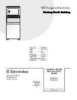
InnoClean PLUS
Kleinkläranlage zum Einbau
ins Erdreich
in den Nenngrößen
EW 4 bis EW 50
Installation
der Anlage wurde durchgeführt von Ihrem Fachbetrieb:
Inbetriebnahme
Einweisung
Produktvorteile
Bedienungsanleitung Seite
1
Instructions de Montage
Page 47
Installation Manual
Page 92
Anleitung kann über
www.kessel.de
im Format DIN A 4
heruntergeladen werden!
Instrukcja Zabudowy
strona 137
Istruzion per l’installazione
pagina 182
KESSEL-Kleinkläranlagen
InnoClean PLUS
- die vollbiologische Kleinkläranlage
zur Reinigung häuslichen Abwassers
nach EN 12566, Teil III
Handleiding voor montage
pagina 227
D
F
GB
PL
I
NL
Summary of Contents for InnoClean PLUS EW 10
Page 2: ...2 ...
Page 40: ...12 CE Konformitätserklärung Leistungserklärung 40 ...
Page 85: ...85 12 Certificat de conformité declaration de performance ...
Page 130: ...12 Declaration of performance conformity 130 ...
Page 175: ...175 12 Deklaracja zgodności ...
Page 176: ...176 12 Deklaracja zgodności ...
Page 220: ...220 12 Dichiarazione di conformità CE ...
Page 221: ...221 12 Dichiarazione di conformità CE ...
Page 265: ...265 12 Verklaring van conformiteit ...
Page 266: ...266 12 Verklaring van conformiteit ...
Page 273: ...273 Verrohrung Tuyauteries Pipework Rury Tubazioni Leidingen ...
Page 274: ...Verrohrung Tuyauteries Pipework Rury Tubazioni Leidingen 274 France ...
Page 275: ...Verrohrung Tuyauteries Pipework Rury Tubazioni Leidingen France Retour de boues ...