* Refer to parts list on page 25.
Refer to DM-SE7/SE9 (B51-5395-00) and
DM-5090/9090 (B51-5387-00) service manu-
als if require circuit description.
MINI DISC RECORDER
DM-S500
SERVICE MANUAL
© 1997-11/B51-5398-00 (K/K) 2456
7
3
8
¡
1
÷
REC
REC
INPUT
REC
LEVEL
ON/STANDBY
MINI DISC RECORDER DM-S500
0
TIME
DISPLAY
¢
4
L
R
L
R
REC
IN
DIGITAL IN
LINE
OPTICAL
1
2
PLAY
OUT
SYSTEM
CONTROL
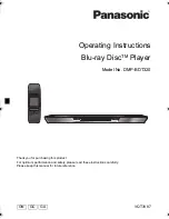
Dressing panel
(A21-3620-02)
Dressing panel
(A21-3622-03)
Dressing panel
(A21-3623-03)
Dressing panel
(A21-3621-03)
Indicator
(B12-0329-04)
Miniature phone jack
(E11-0188-05)
AC power cord *
(E30-)
Optic receiving module
(W02-1181-05)
Power cord bushing
(J42-0083-05)
Phono jack
(E68-0120-05)
Metallic cabinet
(A01-3444-01)
Front glass
(B10-2386-12)
Knob
(K29-6835-12)
Knob
(K29-6835-12)
Knob
(K29-6835-12)
Knob
(K29-6945-04)
Panel *
(A60-)
In compliance with Federal Regulations, following are reproduc-
tions of labels on, or inside the product relating to laser product
safety.
KENWOOD-Crop. certifies this equipment conforms to DHHS
Regulations No. 21 DFR 1040. 10, Chapter 1, Subchapter J.
DANGER : Laser radiation when open and interlock defeated.
AVOID DIRECT EXPOSURE TO BEAM
DM-S500(K)
COVER(
98.4.24
9:35
PM
y [ W
2