DE Einbau- und Bedienungsanleitung
KEMPER Filter Modul F
Figur 712 0G, DN 15 - DN 50
KEMPER Druckminderer-Filter-Kombination Modul DMF
Figur 713 0G, DN 15 - DN 50
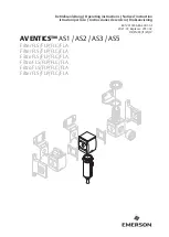
EN Installation and Operation Manual
KEMPER Module F Filter
Figure 712 0G, DN 15 - DN 50
KEMPER Module DMF pressure reducing valve-filter combination
Figure 713 0G, DN 15 - DN 50
!
2
18
Fig. 713 0G
Fig. 712 0G