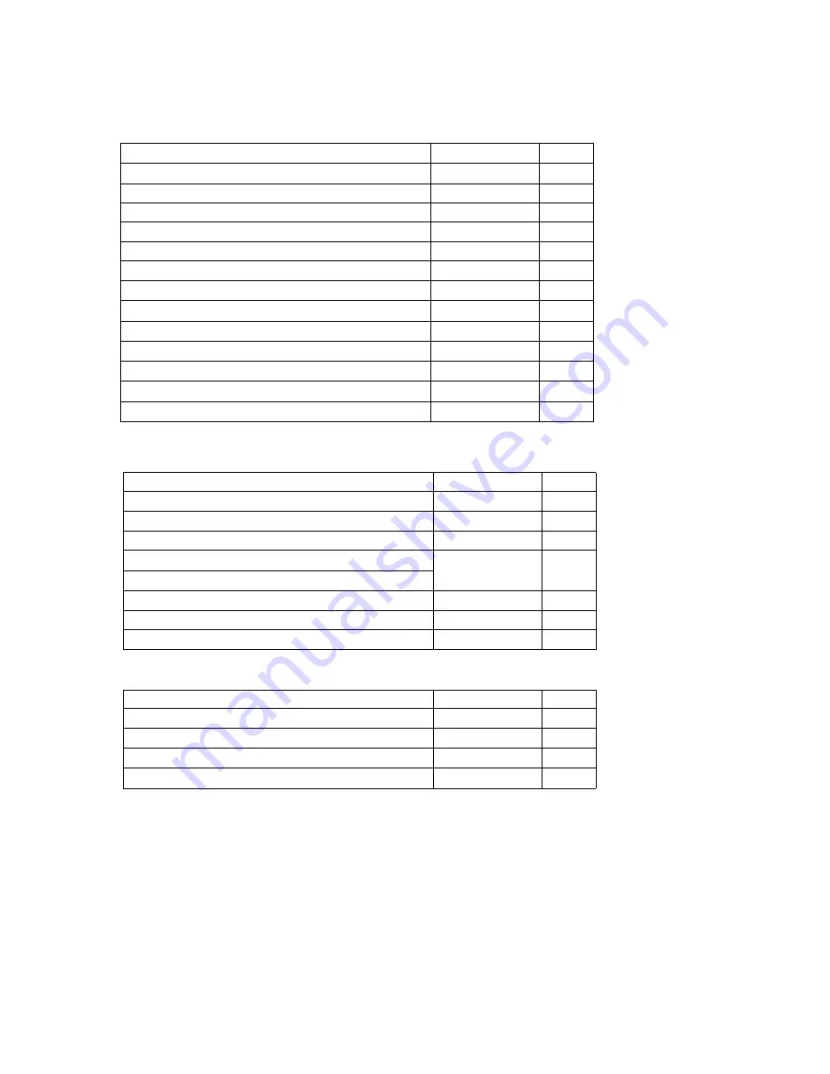
background image

Component List

Standard

Optional Extras

ITEM

MODEL

QTY

Carrying Case

3910-01

1

Lithium-ion Battery

3910-09

1

Battery Charger

3910-10

1

Air Velocity Probe

6531

1

Temperature and Humidity Probe

Differential Pressure Sensor

C264 100Pa

1

Differential Pressure Sensor Cable

3900-02

1

Contact Output Cable

3900-03

1

Consumables

ITEM

MODEL

QTY

Zero Filter (w/t joint and tube (70cm))

3910-04

1

Printer Paper (Dust Free Paper)

3910-05

1

Standard Inlet

3910-06

1

Isokinetic Suction Probe

3910-07

1

For more information on consumables, please contact your distributor or your KANOMAX service center.

ITEM

MODEL

QTY

Main Unit

3910-01

1

Power Card

-

1

Standard Inlet

3910-06

1

Isokinetic Suction Probe

3910-07

1

Zero Filter

3910-04

2

Tygon Tube (2M)

-

1

Printer Paper (Dust Free Paper)

3910-05

2

Measurement Software

-

1

Operation Manual

-

1

Test Certificate

-

1

AC adapter(GS60A15)

3910-08

1

USB flash drive

– 16GB

-

1

Lithium-ion Battery

Li202SX-7800

3910-09

1

Summary of Contents for 3910

Page 1: ...d tube 70cm 3910 04 1 Printer Paper Dust Free Paper 3910 05 1 Standard Inlet 3910 06 1 Isokinetic Suction Probe 3910 07 1 For more information on consumables please contact your distributor or your KANOMAX service center ITEM MODEL QTY Main Unit 3910 01 1 Power Card 1 Standard Inlet 3910 06 1 Isokinetic Suction Probe 3910 07 1 Zero Filter 3910 04 2 Tygon Tube 2M 1 Printer Paper Dust Free Paper 391...

Page 2: ...on including the use of optical instruments for intrabeam viewing Laser Safety Instruction Danger This instrument employs a laser inside the unit as the light source of the sensor Never open close the case of the unit or disassemble the optical sensor inside the unit Caution Use of controls adjustments or performance of procedures other than those specified herein may result in hazardous radiation...

Page 3: ...ide or near this symbol e g The symbol shown to the left prohibits disassembly Indicates a mandatory action A specific action is described near the symbol WARNING Do not disassemble modify or repair the instrument A 3B laser diode is used as the optical source inside the instrument Therefore never attempt to disassemble the instrument as it is extremely dangerous Also disassembling the unit may re...

Page 4: ...ult in damage to battery or internal circuitry Dispose the battery according to local law or regulation In case of explosion don t throw the battery to fire Don t expose the battery under any high temperature such as radiator direct sunlight Don t crack or try to disassemble the battery CAUTION Remove battery when the instrument will not be used for an extended period of time Also do not leave a d...

Page 5: ...nt circuitry Do not let the instrument suck in highly concentrated particles that exceed the specification level Failure to observe the above may contaminate the instrument As a result the instrument may fail to obtain zero count In order to check the performance under highly concentrated environments make sure to attach the filter to the inlet If you accidentally let the instrument suck in highly...

Page 6: ...n 7 3 2 1 Log In Display 7 3 2 2 User 7 3 2 3 Authentication 8 3 2 4 Log 8 3 3 Initial Screen 9 3 3 1 Initial Screen 9 3 3 2 Screen Change Initial Screen 14 3 4 MONITOR 15 3 5 MODE 16 3 5 1 SINGLE 16 3 5 2 CONTINUOUS 19 3 5 3 INTERVAL 20 3 5 4 STATS 22 3 5 5 STANDARD 24 3 5 6 PRESET 27 3 5 7 REMOTE 27 3 6 START 28 3 6 1 SINGLE CONTINUOUS INTERVAL 28 3 6 2 STATS 30 3 6 3 STANDARD 35 3 6 4 Interlock...

Page 7: ... Connecting Option Sensors 67 6 Printing Examples 68 6 1 Printing Example for Each Measurement Mode 68 6 1 1 SINGLE 68 6 1 2 CONTINUOUS 68 6 1 3 INTERVAL 69 6 1 4 STATS 70 6 1 5 STANDARD 71 7 Battery Charge 72 7 1 Charging Battery 72 8 Main Specifications 73 9 Troubleshooting 74 10 Warranty and After sales Service 76 ...

Page 8: ...n the LCD screen and can be stored in the internal memory of the instrument and be printed out by the internal printer As for the power supply either an AC adapter 100 240V or batteries can be used 1 2 Airborne Particle Counter FRONT Power Switch you can turn the power on or off by using this button Inlet Particles enter the unit from here Attach the provided standard inlet To use the provided iso...

Page 9: ...t AC adapter with an AC output with protective earthling Optional Sensor Connecting Terminal Terminals where optional sensors can be connected Refer to 5 Connecting Option Sensors for details ETHERNET Connector To be used when controlling the instrument by the software For details refer to the operation manual for the software MEMORY CARD Insertion Slot Insert the MMC card to store measurement dat...

Page 10: ... the screw on the cover to open it Connect the battery to the connecter inside the compartment Insert the battery as shown to the right picture the connecter end should go to the rear of the compartment The cover back and tighten the screw to fix the cover When you insert the AC adapter the Power state LED will light up and show red color And when the batteries are charging the red LED will blinki...

Page 11: ... prevent particles from entering the instrument Perform a measurement for one minute and then perform a Zero Check Refer to 3 4 MONITOR for the operation procedure Perform a Zero Check at least once a day It is recommended a Zero Check be done before and after each measurement 2 3 Isokinetic Suction Probe Use the Isokinetic Suction Probe to ensure the sampling air velocity is equivalent to the ope...

Page 12: ...o that a slight portion is sticking out of the printer when the cover is closed 1 3 2 2 4 2 Zero Filter Replacement If the performance of the provided zero filter is deteriorated please purchase a new Zero Filter To replace a Zero Filter refer to 2 2 Zero Check 2 4 3 Isokinetic Suction Probe Replacement If the provided Isokinetic Suction Probe is damaged or lost or any air leak is detected please ...

Page 13: ...ion Procedure 6 3 Display Description and Operation Procedure 3 1 Boot Screen A few seconds after the instrument is turned ON the screen shown to the left will be displayed Please wait for a few moments while the system is initialized ...

Page 14: ... to be 4 to 16 alphanumeric characters Passwords expire every 180 days after which the user ID will be invalid until a new password is set Qualification Each user is granted authorization to perform certain operations For example if a user has authorization for Change Measurement Setting operation the user cannot change the measurement settings If the current logged in user does not have the autho...

Page 15: ...ired for other activities If a user fails to log in three times the user ID will become invalid 3 2 4 Log The instrument saves a history of operations error messages and alarms in the log file The operation log stores the time User ID operation detail result and parameter of the occurrence A user can review logs on the Log Maintenance screen Authentication required Please refer 3 8 3 Other for det...

Page 16: ...the left will be displayed All operations can be started from this screen When the measurement parameters are displayed you can tap the switch button to show the ambient parameters if an option sensor is attached Tap the title to switch between data graph and map When a chart is displayed users can change the particle chart to the ambient chart by tapping the button 2 1 3 4 ...

Page 17: ...urement data MENU Configures chart settings alarm settings and system settings Icons in the Status Display Indicates if the instrument is powered by the AC power cord or a battery If it s battery powered the remaining battery level is also shown Indicates a pump error status If the pump is operating abnormally this icon will be shown Indicates an LD error status If the LD is operating abnormally t...

Page 18: ...Charts Switches the display between the particle chart and the OP sensor chart on the GRAPH screen Scrolls the chart to the left half of the display can be scrolled at a time Scrolls the chart to the right half of the display can be scrolled at a time ...

Page 19: ...fer to 3 8 1 MEASURING CHART SETTING In the display shown above LOG is selected for the scale of the Y axis and the maximum scale value of the Y axis is set to 10 to the sixth Option Sensor Graph Example Select one of the three combinations of minimum and maximum scale values of the Y axis for each sensor For setting the combination of minimum and maximum values please refer to 3 8 1 MEASURING CHA...

Page 20: ...s to 10 20 Sets the maximum scale value of the X axis to 20 50 Sets the maximum scale value of the X axis to 50 100 Sets the maximum scale value of the X axis to 100 150 Sets the maximum scale value of the X axis to 150 300 Sets the maximum scale value of the X axis to 300 ALL Displays all data ...

Page 21: ...3 Display Description and Operation Procedure 14 3 3 2 Screen Change Initial Screen MONITOR MODE RETURN MONITOR START STOP MENU EXIT FILE CLOSE ...

Page 22: ...t if the pump is already operating sampling will start immediately when you tap MONITOR Note that the instrument is capable of 180 hours of continuous operation While measuring tap MONITOR again A dialog will be displayed asking you if you want to stop monitoring Tap Yes to stop monitoring Note that you cannot save measurement data or display the chart when you are monitoring in this mode ...

Page 23: ...MPLE T CYCLES MANUAL STOP AUTO SAVE AUTO PRINT and START DELAY Please note that the setting items vary depending on the measurement mode 3 5 1 SINGLE Measurement Flow Perform a measurement once within the pre set time frame Example If the setting is as follows INTERVAL N A SAMPLE T 00 00 15 CYCLES N A A 15 second sampling is performed Delay Time Set Delay Time in START DELAY screen Refer to 3 8 1 ...

Page 24: ... 1 for details Below is a breakdown of the Wait Time Did you set Delay Time Counting down Delay time Display Waiting Is Pump working Pump is turned on Display Preparing Measurement starts 10 sec to go Display Measuring Is Pump working Pump is turned on Wait for 10 sec Display Preparing Wait for 10 sec YES NO YES NO NO YES NO YES ...

Page 25: ...RT DELAY to use a delay time prior to a measurement Check Set time to set the time when you want to start a measurement Tap OK c to save and activate the settings Authentication required PRESET Tap PRESET d on MEASURE SETTING dialog box to display a window asking you to input PRESET NAME Tap the entry field e to display the keyboard Enter the file name and tap Enter f Tap OK to save the current se...

Page 26: ... to use a delay time prior to a measurement Check Set time to set the time when you want to start a measurement Tap OK to save and activate the current settings Authentication required PRESET Tap PRESET to display a window asking you to input PRESET NAME Tap the entry field to display the keyboard Enter the file name and tap Enter Tap OK to save the current settings on the USB flash drive Authenti...

Page 27: ... MANUAL STOP To set INTERVAL and SAMPLE T tap the entry field to display a numeric keypad Enter hours minutes and seconds and tap OK Tap the entry field for CYCLES to display a numeric keypad Tap the value you want to enter and tap Enter Check MANUAL STOP to continue measuring until you stop measuring regardless of the CYCLES setting Check AUTO SAVE to store the data automatically Check AUTO PRINT...

Page 28: ... input PRESET NAME Tap the entry field to display the keyboard Enter the file name and tap Enter Tap OK to save the current settings on the USB flash drive Authentication required In the future you can automatically load the configuration saved here as a PRESET Refer to 3 5 6 PRESET Input PRESET NAME ...

Page 29: ...ENTER Once a MAP file is loaded you cannot change the settings for SAMPLE POINT The configured number of measurement points in the MAP file will be applied When a MAP file is not loaded tap an entry field of SAMPLE POINT to display a numeric keypad Enter a value and tap ENTER PRESET Tap PRESET to display a window asking you to input PRESET NAME Tap the entry field to display the keypad Enter the f...

Page 30: ...der Tap the Location to be changed Use the and buttons to change the order Tap OK Then a window will be displayed asking if you want to save the new order of the Location Tap Yes or No Authentication required Tap Yes to set the changes and go back to MEASURE SETTING screen Tap No to go back to MAP screen Tap CANCEL to discard the changes and go back to MEASURE SETTING screen ...

Page 31: ...E POINT to repeat measurements INTERVAL and SAMPLE T are configured with the same value Measurements are repeated according to the CYCLES setting in each SAMPLE POINT After the all the measurements are finished the results are evaluated according to the selected standard Tap STANDARD to open the SELECT STANDARD window to select a measurement standard to be applied in the STANDARD mode Select and s...

Page 32: ...n the EXTENTION tab configure the following ROOM STATUS AIR DIRECTION only for Federal Standard COMMENT AIR DIRECTION Select unidirectional when wind direction is constant Select nonunidirectional when wind direction is not constant ROOM STATUS Select either as built as rest or operational Select as built when the cleanroom is setting up Select as rest when the cleanroom function is off Select ope...

Page 33: ...oading a saved PRESET Authentication required Refer to 3 5 6 PRESET Tap the MAP button to display MAP You can change the location order by tapping the Location to be changed and then using the and buttons Tap OK Then a window will be displayed asking if you want to save the new order of the Locations Tap Yes or No Tap Yes to save the changes and go back to MEASURE SETTING screen Authentication req...

Page 34: ... name indicates the mode type SG SINGLE MEASUREMENT CO CONTINUOUS MEASUREMENT IN INTERVAL MEASUREMENT ST STATS MEASUREMENT IS STANDARD MEASUREMENT Select the item that you want to load or delete Tap OK to load the selected PRESET settings into MODE and MEASURE SETTING Authentication required Tap DELETE to delete the selected PRESET setting Authentication required 3 5 7 REMOTE Change to REMOTE MODE...

Page 35: ...ng the last 10 seconds of that Delay Time the pump will run to stabilize after which the measurement will begin If START DELAY and Set time are checked in MODE setting Upon tapping START Input START TIME dialog box will be displayed Enter the time when you want to start measuring and tap OK During the last 10 seconds of the Time left time the pump will run to stabilize after which the measurement ...

Page 36: ...ple in each Measurement MODE SINGLE MODE CONTINUOUS MODE After a measurement in INTERVAL mode is finished the measurement results will be displayed INTERVAL MODE After measurement is finished To display the chart tap button while measuring Tap STOP to stop a measurement ...

Page 37: ...egins During the last 10 seconds of that Delay Time the pump will run to stabilize after which the measurement will begin If START DELAY and Set time are checked in MODE setting Upon tapping START Input START TIME dialog box will be displayed Enter the time when you want to start measuring and tap OK During the last 10 seconds of the Time left time the pump will run to stabilize after which the me...

Page 38: ...nt point Tap PRINT to print the measurement results When all of the measurements are finished a final measurement result will be displayed You can view the results of a certain LOCATION by selecting a Location from the dropdown list of Location Tap CLOSE to end the measurement Tap REMEASURE to perform a measurement again at the last measurement point Tap PRINT to print measurement results of the l...

Page 39: ...p ZOOM to enlarge a MAP Press NORMAL to return to viewing the entire MAP when a map is enlarged Select a Location and tap DETAIL to view the image of the selected Location You need to register the image for the DETAIL view when creating a Schedule using the provided PC application When a MAP is enlarged SCROLL UP SCROLL DOWN SCROLL LEFT and SCROLL RIGHT buttons are activated which enables you to m...

Page 40: ...hich the measurement will begin If START DELAY and SET time are checked in MODE setting Upon tapping START Input START TIME dialog box will be displayed Enter the time when you want to start measuring and tap OK During the last 10 seconds of the Time left time the pump will run to stabilize after which the measurement will begin Tap CANCEL to stop measuring and go back to the menu screen If you fa...

Page 41: ...en all measurements are finished the final measurement results will be displayed You can view the results of a certain LOCATION POINT by selecting Location from the dropdown list of LOCATION Tap CLOSE to end the measurement Tap REMEASURE to perform a measurement again at the last measurement point Tap PRINT to print measurement results of the last measurement point Every time you tap this button t...

Page 42: ...s During the last 10 seconds of that Delay Time the pump will run to stabilize after which the measurement will begin If START DELAY and Set time are checked in MODE setting Upon tapping START Input START TIME dialog box will be displayed Enter the time when you want to start measuring and tap OK During the last 10 seconds of the Time left time the pump will run to stabilize after which the measur...

Page 43: ... CONFIRM window informing you of the next measurement point and wait for the next measurement Tap REMEASURE to perform a re measurement Tap STOP to stop a measurement Tap PRINT to print a measurement result Tap START to start a measurement Tap STOP to stop a measurement Tap button while measuring to display a chart Tap STOP to stop a measurement CONFIRM window ...

Page 44: ...p EVAL to display CLEAN ROOM EVALUATION window Tap REMEASURE to perform a re measurement Tap PRINT to print a measurement result Tap PRINT to print a measurement result By selecting particle size you can change the particle size of the data to be evaluated However the status indicated by RESULT is determined based on the particle size selected in MODE settings Tap CLOSE to close the window Measure...

Page 45: ... on the settings configured in 3 5 MODE Select a Location and tap START to start a measurement Tap STOP to stop a measurement Tap ZOOM to enlarge a MAP Press NORMAL to return to viewing the entire MAP when a map is enlarged When a MAP is enlarged SCROLL UP SCROLL DOWN SCROLL LEFT and SCROLL RIGHT buttons are activated which enables you to move the MAP ...

Page 46: ...0 seconds of that Delay Time the pump will run to stabilize after which the measurement will begin If START DELAY and Set time are checked in MODE setting Upon tapping START Input START TIME dialog box will be displayed Enter the time when you want to start measuring and tap OK During the last 10 seconds of the Time left time the pump will run to stabilize after which the measurement will begin Ta...

Page 47: ...t results The color of a location changes from green to red once a measurement is done When all measurements are finished the final measurement results will be displayed You can view the result of a certain LOCATION POINT by selecting Location from the dropdown list Tap EVAL to display CLEAN ROOM EVALUATION screen Tap REMEASURE to perform a re measurement at the current location Tap PRINT to print...

Page 48: ... size Tap to return to displaying data for all 6 particle sizes SINGLE and CONTINUOUS mode Tap to switch to displaying a chart while measuring A particle size based histogram will be displayed in SINGLE and CONTINUOUS modes Tap again to return to displaying data for all 6 particle sizes Every time you tap the particle unit it changes in the order of CNT cf m3 ...

Page 49: ...TS and STANDARD modes A time series chart will be displayed in INTERVAL STATS and STANDARD modes Tap to switch to the Single display Tap to return to the Total display For details on Total display and Single display please refer to P10 Icons in the Status Display ...

Page 50: ...K F L O V and B Each means OK No error F FLOW error L LD error O OPTION SENSOR error V OVER B BATTERY error Message when printing While data is being printed the message shown to the left will be displayed If you tap STOP you can cancel the printing However the data already transmitted to the printer will be printed ...

Page 51: ...a measurement will be discarded when the power goes OFF INTERVAL Mode Data taken before electricity goes out remains stored in the instrument When restarting the instrument the message shown below will be displayed Tap YES to save the data The calculation data will be created using the data collected before the power went out Tap NO to discard the data STATS and STANDARD Mode Data taken before ele...

Page 52: ...ge the measurement mode or MODE settings STATS If you start a measurement when the instrument is in a temporary state of suspension the message below will be displayed Tap YES to resume measuring from the next LOCATION If you tap NO you will get a message asking if you want to save the data or not Tap CANCEL to go back to the main screen If you tap NO on the window above a confirmation window will...

Page 53: ...yed Tap YES to resume measuring from the next LOCATION Tap NO to display CLEAN ROOM EVALUATION Then the measurement will be completed Tap PRINT to print out the result Tap CANCEL to close the CLEAN ROOM EVALUATION window If you try to switch the mode the message below will be displayed Tap OK You cannot change the mode when a measurement is in a temporary state of suspension ...

Page 54: ...ODE to narrow down the files to be displayed c After you select the file that you want to display the file name will be displayed in the box for FILE NAME Then tap OK to open the data display screen as shown below Tap CALC DATA tab to display CALC result Tap SETTING tab to display the setting information e To delete the displayed file tap DELETE A dialog will be displayed asking you if you want to...

Page 55: ...o that you can check the file s that you want to delete b Use MEASURE MODE to narrow down the files to be deleted c Select the file s that you want to delete and tap OK Authentication required The User needs the authorization Delete Files to delete files For data protection purpose files can be only deleted after they have been copied a Select the MOVE button to move files from internal data stora...

Page 56: ... configure the following settings CHART PRINT ALARM OPTION SENSOR START DELAY MESSAGE CHART SETTING Configure the axis of the chart and range settings For X Axis select either 10 20 50 100 150 or 300 For Y Axis in PARTICLE tab select either LOG or LINEAR Select 1 2 3 or 4 to determine which of the Y AXIS MAX values will be displayed on the chart You can set 4 different max values each for LOG and ...

Page 57: ...alues and close the window Authentication required Tap CANCEL to discard any changes you ve made to the values and close the window The previous values will be applied Select 1 2 or 3 to determine which of the 3 value settings will be displayed on the chart MAX value set in the PARTICLE tab in the CHART SETTING window is applied to the chart Tap the MAX value to change it It changes in the order o...

Page 58: ...et in the OPTION tab in the CHART SETTING window is applied to the chart Tap MAX value to change it It changes in the order of 10 20 50 100 150 and 300 The MAX and MIN values set for each sensor in the OPTION tab in the CHART SETTING window is applied in the chart Tap MAX or MIN value to change it It changes in the order of MIN MAX settings 1 2 and 3 ...

Page 59: ...sensor In CALC DATA tab you can configure the following settings CALC data printing ON OFF Particle size s to be printed out Option sensor data printing ON OFF Check CALC DATA INCLUDED to print calculated data MAX MIN and AVE Check particle size of the data that you want to print out Check OPTION to output data of the option sensor s In EVAL DATA tab configure the following setting EVAL data print...

Page 60: ...at you want to trigger the alarm To enter the threshold tap the entry field to display a numeric keypad Enter a value and tap Enter In the OPTION tab you can set an alarm threshold for TEMPERATURE HUMIDITY VELOCITY and DIFFERENTIAL PRESSURE Tap the entry field to display a numeric keypad Enter a value and tap Enter To activate the audible alarm check Alarm Sound Tap APPLY to save the settings Auth...

Page 61: ...o use an option sensor check USE NO USE box Tap OK to save the settings and close the window Authentication required Tap CANCEL to discard entries and close the window UNIT Set the unit for TEMPERATURE and VELOCITY For TEMPERATURE select C or F For VELOCITY select m sec or FPM MIN MAX Set the measurable range of the sensor according to the specifications of each option sensor Tap an entry field to...

Page 62: ...OK to activate the settings Authentication required MESSAGE SETTING In the MESSAGE SETTING window you can choose whether or not to display messages for PREPARATION and DELAY Tap OK in order to activate the settings Authentication required PREPARATION will display a message after the pump is ON before sampling starts DELAY will display a message before sampling starts when START DELAY function is O...

Page 63: ...se the buttons to adjust the selected number Tap OK to activate the settings Authentication required LCD In the LCD settings configure the Power saver time out and Brightness setting Also the LCD displays the power state of the unit battery level power source AC battery battery charging etc For the Power saver time out setting select one among 1min 2min 5min 10min 15min 30min To configure the brig...

Page 64: ...nsole or remote mode For the HOST NAME enter a name to identify the instrument when it is connected to a network or workgroup by Ethernet Be sure not to use the same name as other PCs or devices on the network or workgroup For IP ADDRESS check AUTO to acquire an IP ADDRESS automatically If AUTO is unchecked enter IP Address NET MASK and DEFAULT Gateway Tap OK to save the settings and to close the ...

Page 65: ...ng files Tap OK to save the settings and close the window Authentication required Tap CANCEL to discard the current settings When transferring data and other files to a PC different date time or timestamp will be displayed if the setting of time zone is different from the one in the PC Having the pump always on eliminates the PREPARATION time before sampling However it increases the chances of the...

Page 66: ...er information User Setting window shows registered users Select one of the registered users displayed on the screen and tap DELETE to delete the selected user Authentication required Select one of the registered users displayed on the screen and tap PRINT to print out the selected user information Tap REGISTER to register a new user Authentication required Select one of registered users and tap M...

Page 67: ...emo up to 99 characters h Qualification Check the items to set user authorizations Administrators automatically have authorization to perform all tasks Items i j and k show when a user edits user information i Password expiration Shows the expiration date of the password Passwords expire every 180 days The default Administrator password needs to be changed within 60 days j Registration date Shows ...

Page 68: ... Files Allows a user to copy data such as measurement data log data and user information Data can be copied via network Delete Files Allows a user to delete data such as measurement data and user preset files View Logs Allows a user to review the log data Input Password Edit password from INPUT PASSWORD screen The keyboard shows up when the user taps entry fields a OLD Password type in the current...

Page 69: ...n Date Time User ID Operation requests and results and Parameters b User ID Select user ID to review the user s logs c Operation Alarm Error Select the type of log from the following Operation shows operation logs Alarm shows alarm logs Error shows error logs d Date Select start date and end date for logs Tap Update to refresh the log list which is based on the criteria you select in b c and d Tap...

Page 70: ...e remaining capacity of the internal data storage REMOTE MODE SETTING In the REMOTE MODE SETTING check START IN REMOTE MODE to activate remote mode automatically when the instrument is turned ON Enter remote address in the entry field for ID Tap OK to save the settings and close the window Tap CANCEL to discard changes ...

Page 71: ... after a user ID and password are inputted you return to MENU screen Tap SHUTDOWN A window will be displayed asking Do you want to shut down the power 5 seconds after tapping YES the instrument will shut down Make sure to turn the power off at the LOG IN screen If the power is not turned off from the LOG IN screen settings or data loss as well as hardware errors may occur 3 8 5 EXIT Go back to the...

Page 72: ...ord as registered in the instrument To transfer data to a PC using the USB flash drive select COPY in the FILE SELECT window to transfer data files and COPY in the LOG MANAGEMENT window to transfer log files Select EXPORT in the USER MANAGEMENT window to transfer user information files User needs the authorization Copy Files to copy files To update the user information file on the instrument in th...

Page 73: ...les to copy files 4 4 Remote Measurement You can read data stored in the instrument directly from PCs connected via network to take measurements You need to connect the instrument to the network and make appropriate settings in the COMMUNICATION SETTING Before taking remote measurements START IN REMOTE MODE needs to be checked in the REMOTE MODE SETTING window which can be displayed from the CONTR...

Page 74: ...ansmitter cable MODEL 3900 02 is required separately Please check with your sales representative Temperature Humidity Velocity Probe Model 6531 Temp Range 20 to 70 C Temp Accuracy 0 5 C Humidity Range 2 to 98 RH Humidity Accuracy 2 RH when in the range of 2 80 RH other 3 Velocity Range 0 01 to 30 m s Velocity Accuracy 2 of reading or 0 015m s whichever is greater Dimension Φ10 to 16 x212 mm Length...

Page 75: ...ax Particle p Total TIME 0 3um 0 5um 1 0um 12 00 00 8000 5000 3000 TIME 3 0um 5 0um 10 0um 12 00 00 1000 500 100 TIME T C H V m s P Pa 12 00 00 25 2 68 5 0 1 15 SG20101201120000 Ser No 654321 Measured by kanomax Measured on 12 01 2010 Sample Time 00 01 00 Repeats 1 Printed by kanomax Particle p Total TIME 0 3um 0 5um 1 0um 12 00 00 8000 5000 3000 TIME 3 0um 5 0um 10 0um 12 00 00 1000 500 100 TIME ...

Page 76: ...e 90 9 3 0um Min 3 Max 12 Ave 7 4 5 0um Min 0 Max 4 Ave 1 4 10 0um Min 0 Max 2 Ave 0 2 Temperature C Min 24 8 Max 25 3 Ave 25 2 Humidity Min 64 3 Max 68 2 Ave 65 4 Velocity m s Min 0 1 Max 0 3 Ave 0 2 Pressure Pa Min 13 Max 21 Ave 15 Particles p Total TIME 0 3um 0 5um 1 0um 12 00 00 15924 389 92 12 01 00 15623 439 102 12 09 00 15759 521 103 TIME 3 0um 5 0um 10 0um 12 00 00 6 2 0 12 01 00 5 0 0 12 ...

Page 77: ... Min 0 Max 2 Ave 0 2 Temperature C Min 24 8 Max 25 3 Ave 25 2 Humidity Min 64 3 Max 68 2 Ave 65 4 Velocity m s Min 0 1 Max 0 3 Ave 0 2 Pressure Pa Min 13 Max 21 Ave 15 2 Location2 2 5 Start at 12 01 2010 12 25 00 Sample Time 00 00 06 Repeats 10 Print 5 locations Particles p Total TIME 0 3um 0 5um 1 0um 12 00 00 15924 389 92 12 01 00 15623 439 102 Print 25 points 12 45 00 15759 521 103 TIME 3 0um 5...

Page 78: ...m Min 389 Max 521 Ave 441 9 1 0um Min 57 Max 103 Ave 90 9 3 0um Min 3 Max 12 Ave 7 4 5 0um Min 0 Max 4 Ave 1 4 10 0um Min 0 Max 2 Ave 0 2 Temperature C Min 24 8 Max 25 3 Ave 25 2 Humidity Min 64 3 Max 68 2 Ave 65 4 Velocity m s Min 0 1 Max 0 3 Ave 0 2 Pressure Pa Min 13 Max 21 Ave 15 2 Location2 2 5 Start at 12 01 2010 12 25 00 Sample Time 00 00 06 Repeats 10 Print 5 locations Particles p Total TI...

Page 79: ...when the power is on and the battery is charging you can follow this instruction First tap the Power Icon a on the main screen Tap Enable Pull b and then you can pull the batteries out or insert them When you are finished you must tap RETURN c to finish it You may also charge the battery with the provide charger instead of using the instrument and AC adapter Open the battery compartment cover on t...

Page 80: ... 1 000 times 100 bytes 1 000 times 100k bytes Up to 10 000 files can be stored Printer Built in Compatible with Dust free Paper Interface Ethernet Power Supply AC adapter 100 to 240V Rechargeable Lithium ion battery 2 battery slots Provides 5 hours of continuous usage from 2 fully charged batteries User replaceable Operating Environment This model can be used in the environment described below Tem...

Page 81: ... the instrument under the environmental conditions set in the specifications If you have checked the above 1 2 and 3 and the instrument readings are still too high the instrument may require calibration or repair Contact your distributor or your KANOMAX service center for repair or calibration Count value is too low Lower than the expected 1 The particle count at the measurement site may be low 2 ...

Page 82: ...et are not blocked The pump may be damaged Return the instrument to your distributor or to your KANOMAX service center for repair BATTERY ERR Power capacity is low If using a rechargeable battery charge the battery If using the AC line the line may have problems OVER ERR The operating environment may be outside the range defined in the specifications The inside of the optical system may be dirty A...

Page 83: ...buse mishandling improper packaging by the owner alteration accident electrical current fluctuations failure to follow operating maintenance or environmental instructions prescribed in the PRODUCT s instruction manual provided by KANOMAX or service performed by a party other than KANOMAX NO IMPLIED WARRANTY INCLUDING ANY IMPLIED WARRANTY OF MERCHANTABILITY OR FITNESS FOR A PARTICULAR PURPOSE APPLI...

Page 84: ...od of five 5 years after production cessation of the PRODUCT This storage period of repair parts is considered as the period during which KANOMAX can provide repair service For more information please contact your sales representative When you call please have the following information at hand 1 PRODUCT name 2 Model number 3 Serial number 4 Probe number 5 Description of Symptom and 6 Date of purch...

Page 85: ...ales kanomax co jp China Shenyang Kano Scientific Instrument Co Ltd No 12 4 Jia Wencui Road Heping District Shenyang City PRC TEL 86 24 23845309 FAX 86 24 23898417 URL http www kanomax com cn E Mail sales kanomax com cn Copyright Kanomax Japan Inc All rights reserved 2016 No copying distribution publication modification or incorporation of this document in whole or part is permitted for commercial...

Reviews: