Kaba 5 00 Series, Installation Instructions Manual
The Kaba 500 Series is a premium lock system designed for commercial buildings. Ensure a flawless installation with the comprehensive Installation Instructions Manual. Download this manual for free from our website, providing step-by-step instructions and expert guidance to maximize the efficiency and security of your Kaba lock. manualshive.com
Share
Download


Reviews:
No comments
Related manuals for 5 00 Series

ICELOCK 544 Series
Brand: Össur Pages: 75
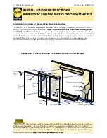
803V0102
Brand: Pella Pages: 12

Peaks Preferred
Brand: Kaba Pages: 92

FullStop Saracen Ultra
Brand: Purple Line Pages: 4

PL728
Brand: QiLocks Pages: 5

SGL
Brand: Eco Pages: 2

Electronic handle SMART with keypad
Brand: SOREX Pages: 2

YDG413A
Brand: Yale Pages: 20

IQLOCKDOWN
Brand: Johnson Controls Pages: 18

PEMKO LP200 Series
Brand: Assa Abloy Pages: 2

Cable lock and key
Brand: Hama Pages: 22

76508L30 Series
Brand: allgood Pages: 5

SL1000A
Brand: Roger Pages: 4

SafeTLock Cobra 1000
Brand: SafeTech Pages: 2

StrikeForce 6211WF
Brand: Von Duprin Pages: 2

DB1260 Series
Brand: FSH Pages: 4

CX33A
Brand: Von Duprin Pages: 8

LE
Brand: Schlage Pages: 33


