SERVICE MANUAL
COPYRIGHT © 2005 Victor Company of Japan, Limited
No.YA363
2005/11
LCD FLAT TELEVISION
YA363
2005
11
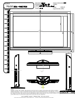
LT-40FH96
/S
TABLE OF CONTENTS
1
PRECAUTION. . . . . . . . . . . . . . . . . . . . . . . . . . . . . . . . . . . . . . . . . . . . . . . . . . . . . . . . . . . . . . . . . . . . . . . . . 1-3
2
SPECIFIC SERVICE INSTRUCTIONS . . . . . . . . . . . . . . . . . . . . . . . . . . . . . . . . . . . . . . . . . . . . . . . . . . . . . . 1-6
3
DISASSEMBLY . . . . . . . . . . . . . . . . . . . . . . . . . . . . . . . . . . . . . . . . . . . . . . . . . . . . . . . . . . . . . . . . . . . . . . . 1-9
4
ADJUSTMENT . . . . . . . . . . . . . . . . . . . . . . . . . . . . . . . . . . . . . . . . . . . . . . . . . . . . . . . . . . . . . . . . . . . . . . . 1-16
5
TROUBLESHOOTING . . . . . . . . . . . . . . . . . . . . . . . . . . . . . . . . . . . . . . . . . . . . . . . . . . . . . . . . . . . . . . . . . 1-22
BASIC CHASSIS
FL3
Preliminary
Summary of Contents for LT-40FH96
Page 28: ... No YA363 2 5 2 6 No YA363 ...
Page 180: ...91 ...
Page 181: ...92 ...
Page 183: ...94 Notes ...
Page 184: ...95 Notes ...