background image

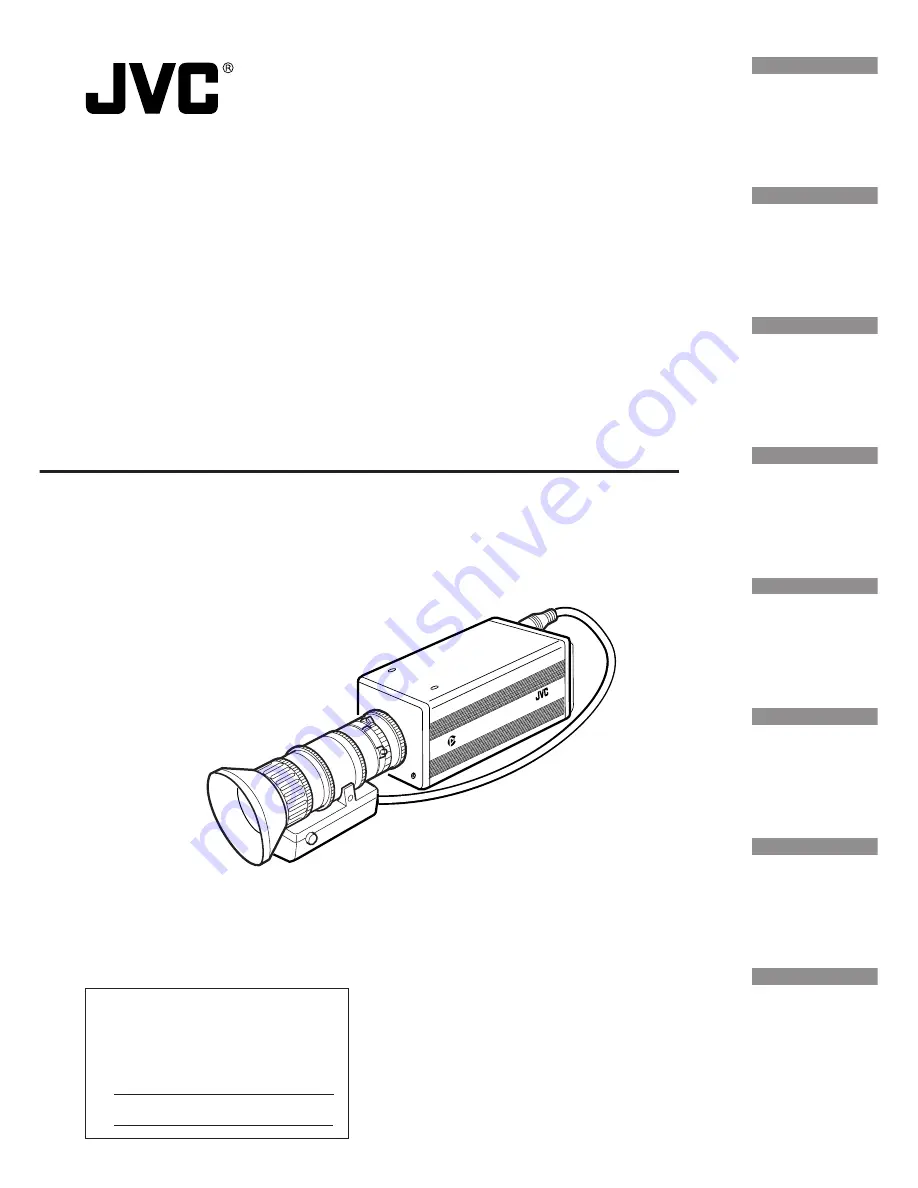
Digital Camera

Model 


KY-F70

INSTRUCTIONS

Illustration with optional lens attachment.

This instruction book is made from 100%
recycled paper.

SC96847-001

KY-F70

CAMERA

DIGITAL

C-MOUNT

For Customer Use:

Enter below the Serial No. which is
located on the unit. Retain this
information for future reference.

Model No. KY-F70

Serial No.

Introduction

Before recording

Settings and

adjustments

for recording

Basic operations

Various

recording

methods

Menu screen

settings

Connecting

 to a PC

Others

Summary of Contents for KY-F70

Page 1: ...96847 001 KY F70 CAMERA DIGITAL C MOUNT For Customer Use Enter below the Serial No which is located on the unit Retain this information for future reference Model No KY F70 Serial No Introduction Before recording Settings and adjustments for recording Basic operations Various recording methods Menu screen settings Connecting to a PC Others ...

Page 2: ...IC SHOCK DO NOT REMOVE COVER OR BACK NO USER SERVICEABLE PARTS INSIDE REFER SERVICING TO QUALIFIED SERVICE PERSONNEL Information for USA This device complies with Part 15 of the FCC Rules Changes or modifications not approved by JVC could void the user s authority to operate the equipment INFORMATION FOR CANADA RENSEIGNEMENT POUR CANADA This Class B digital apparatus complies with Canadian ICES 00...

Page 3: ...terityp eller en ekvivalent typ som rekommenderas av apparattillverkaren Kassera använt batteri enligt fabrikantens instruktion For Norway ADVARSEL Lithiumbatteri Eksplosjonsfare Ved utskifting benyttes kun batteri som anbefalt av apparatfabrikanten Brukt batteri returneres apparatieverandøren For Denmark ADVARSELI Lithiumbatteri Eksplosionsfare ved fejlagtig håndtering Udskiftning må kun ske med ...

Page 4: ...g an MO drive unit 20 Connecting a printer 21 Mounting the camera 22 Fall prevention 23 3 Settings and adjustments for recording Setting the dip switches Monitor SCSI ID 24 Menu settings VGA model Lens 25 Time and date settings 26 Monitor adjustment 28 Focus adjustment 29 White balance adjustment 30 White shading adjustment 32 4 Basic operations Recording images to the main unit memory 34 Playing ...

Page 5: ...ALANCE screen 51 FREEZE screen 53 PROCESS screen 53 SYSTEM SETTING screen 57 Menu screen of the PLAY mode 59 REC mode quick menu screen 60 Resetting settings 62 7 Connecting to a PC Compatible systems 1 64 Compatible systems 2 65 8 Others Specifications 66 CAUTION Cautionary notes concerning operation of the unit MEMO Reference such as restrictions of features etc Z Reference page or item Characte...

Page 6: ... Output digital still images to an MO drive or recommended printer using SCSI connection Export digital still images to a PC using SCSI connection Remotely control your PC using RS 232C connection Accessories and attachments Battery For time and date backup Z page 16 Power cable 2 m For connecting with AC adapter 8 pin cable Z page 18 Remote plug 10 pin REMOTE terminal plug Z page 12 Ferrite core ...

Page 7: ... radios and televisions or near transformers monitors etc with strong magnetic force Compatible lenses Z page 17 Although the lens mount of this product is a type C mount take caution as there are restric tions on the lenses that can be used This product is not equipped with a back focus adjustment feature Please use a lens equipped with the back focus adjustment feature Caring of the product alwa...

Page 8: ...ng the camera Z page 22 Locking screws for the camera mounting bracket M2 6 6mm 3 units CAUTION Always use the attached screws Using screws that exceed 6mm may result in malfunction of the unit a Screw holes for mounting the camera 1 4 inch Used when mounting the camera to a fixer or rotating platform b Lithium battery case Used to case the lithium battery for time and date backup The lithium batt...

Page 9: ...AW SEL SEND SCSI UP MENU MODE REC ON 1 2 3 4 While the menu screen is being dis played press this button selected item up While an item is selected use this but ton to change the set value Setting in the menu screen Z page 44 e AW SEL DOWN button AW Auto White Press this button to adjust the white bal ance when the light source of the sub ject is changed White balance adjustment Z page 28 SEL Sele...

Page 10: ... select a submenu or confirm a selected item or set value Setting in the menu screen Z page 44 Rear continued SEE INSTRUCTION MANUAL POWER DC IN REMOTE MONITOR LENS FREEZE PLAY SET DOWN AW SEL SEND SCSI UP MENU MODE REC ON 1 2 3 4 Ventilation hole g REC display lamp This lamp lights when in the REC mode During FREEZE this display lamp will flash During the REC mode camera images are outputted to t...

Page 11: ...utputted For the VGA mode you can select be tween the FINE mode of 640 480 pix els 7 5 frames sec or DRAFT mode of 640 240 pixels 30 frames sec in the menu screen Setting the VGA mode Z page 25 k LENS connection terminal Used to connect the lens cable Mounting the lens Z page 17 l POWER display lamp This lamp lights when the power of the main unit is on m DC IN power input terminal Mini DIN 8 pin ...

Page 12: ...2V 10 OPERATION Lens terminal Metal 12 pin female 1 2 8 7 10 6 3 4 5 9 Pin no Signal name 1 NC 2 3 GND 4 NC 5 IRIS CONTROL 6 12V DC 7 IRIS POSITION 8 IRIS AUTO MANU 9 NC 10 NC 11 NC 12 NC 6 7 8 2 1 9 3 4 12 5 10 11 Terminal name FREEZE WEN FLASH Conditions Contact point recommended Rated voltage 5 3V H level 3 5 5 0V L level 0 0 8V CMOS 5V OK TLL not possible Output only when in the SXGA mode Rate...

Page 13: ... negative polarity Zo 100 Ω 14 Vs 3V p p negative polarity Zo 100 Ω 15 NC SCSI terminal Half pitch 50 pin female Pin no Signal name 1 11 GND 12 GND 13 NC 14 GND 15 25 GND 26 DB 0 27 DB 1 28 DB 2 29 DB 3 30 DB 4 31 DB 5 32 DB 6 33 DB 7 34 DBP 35 GND 36 GND 37 GND 38 VC 5 input only 39 GND 40 GND 41 ATN 42 GND 43 BSY 44 ACK 45 RST 46 MSG 47 SEL 48 CD 49 REQ 50 I O 1 5 10 6 11 15 1 26 50 25 ...

Page 14: ...AA P700 ON OFF POWER POWER ALARM SHEET PAPER DATA OPEN CP700DSA MITSUBISHI ONLINE COPY CUT PAPER FEED AA P700 AC MONITOR VIDEO IN SCSI DC IN KY F70 CAMERA DIGITAL C MOUNT Connect to the power supply Z page 18 AC adapter Mount the lens Z page 17 Connect the monitor Z page 19 VGA monitor Connect the MO drive unit Z page 20 MO disk drive Connect the printer Z page 21 Printer recommended Mitsubishi CP...

Page 15: ...N CP700DSA MITSUBISHI ONLINE COPY CUT PAPER FEED AA P700 AC KY F70 CAMERA DIGITAL C MOUNT MONITOR SCSI REMOTE REMOTE DC IN AC adapter Microscope adapter Flash Freeze switch VGA monitor MO disk drive Printer Model name CAUTION Use a 1 2 inch mount microscope adapter To avoid damage to the unit always use an adapter that is 4mm or less from the lens mount side Lens 4mm or less ...

Page 16: ...ting the time and date Z page 26 Remove the screws 2 units using the attached mini screw driver then open the cover Completely insert the lithium battery in the direction of the ar row with the side facing up Make sure that the battery is securely in position by the hold ers as shown in the diagram To remove the battery follow the procedure in reverse C R 2 0 2 5 C R 2 0 2 5 K Y F 7 0 C A M E R A ...

Page 17: ...turns with the lens facing you Ä Slowly turn the lens and after adjusting the position retighten the mount clamp ring 3 Insert the camera cable of the lens into the lens connection terminal on the rear of the main unit then securely fasten The iris control is made automatically from the camera When using a manual iris lens set the IRIS MODE to MANUAL see Z page 48 4 When using the lens remote cont...

Page 18: ...UT MAX 1 25A SEE INST RUCTION MANUAL AC 100V AA P700 AC SEE INSTRUCTION MANUAL POWER DC IN REMOTE MONITOR LENS FREEZE PLAY SET DOWN AW SEL SEND SCSI UP MENU MODE REC ON 1 2 3 4 After inserting the plug completely securely fasten by turning the ring To reduce emission of unwanted electrical waves mount the attached ferrite core as shown in the diagram on the left Mount the ferrite core as close to ...

Page 19: ... systems are turned off Connecting with the power turned on may result in malfunction For the connector commercially available VGA video cable is recommended For the pin assignment see page 13 Explanation of terminals SEE INSTRUCTION MANUAL POWER DC IN REMOTE MONITOR LENS FREEZE PLAY SET DOWN AW SEL SEND SCSI UP MENU MODE REC ON 1 2 3 4 MONITOR terminal ...

Page 20: ...24 pixels regardless whether the monitor in use is VGA or SXGA or whether the VGA mode is set to FINE or DRAFT The maximum allowed length of the SCSI cable is 3m When connecting an MO drive to a PC separate setting of the SCSI ID is required Z Page 64 7 Connecting to a PC It is not possible to simultaneously output the image data to a printer and MO drive SEE INSTRUCTION MANUAL POWER DC IN REMOTE ...

Page 21: ...GA or SXGA or whether the VGA mode is set to FINE or DRAFT The maximum allowed length of the SCSI cable is 3m When connecting an MO drive to a PC separate setting of the SCSI ID is required Z Page 64 7 Connecting to a PC It is not possible to simultaneously output the image data to a printer and MO drive SEE INSTRUCTION MANUAL POWER DC IN REMOTE MONITOR LENS FREEZE PLAY SET DOWN AW SEL SEND SCSI U...

Page 22: ...ging the camera mounting bracket position Mounting method KY F70 CAMERA DIGITAL C MOUNT Rotation prevention hole Camera mounting screw hole Camera mounting bracket When shipped the camera mounting bracket is mounted on the bottom of the unit To mount it on the top of the unit simply remove the 3 locking screws holding the camera mounting bracket CAUTION Always use the screws mounted on the main un...

Page 23: ... Falling of the unit may result in bodily injury To prevent the unit from falling connect the unit to a strong surface with a wire chain etc When connecting such chain use the bracket locking screw hole on the side which the camera mounting bracket is not mounted M2 6 6mm Take special caution to the length of the wire as well 6mm KY F70 CAMERA DIGITAL C MOUNT Fall prevention wire chain Camera head...

Page 24: ...et depending on the used system to set the SCSI ID Default ID 7 Set when connecting a printer or MO drive directly to the main unit When making this setting the main unit will become the host ini tiator Set when exporting images to a PC Make sure that the ID numbers of the connecting devices are not the same When making this setting the PC will become the host initiator and the main unit will beco...

Page 25: ...XPOSURE screen AUTO Set when using an auto iris lens MANU Set when using a manual lens or no lens Default setting AUTO Menu settings VGA mode and lens settings are made from the menu screen EXPOSURE I R I S MODE AUTO NORM 1 AL 0 0 FULL STEP 1 8 P STE I SO 4 0 0 I SO 12 8 I R I S LEVEL 0 AE LEVEL I R I S DETECT I TY I R I S AREA SHUTTER SPEED LEVEL SENCET I V ALC MAX ETT I NG SYSTEM S ON SCREEN FRZ...

Page 26: ...n to white and the month will be displayed in purple to indicate that it can be changed In the same manner as above press the UP or DOWN button to set the month 5 Set the day hour and minute in the same manner The seconds display will display 00 The clock will start when the 00 is displayed in purple and the SET button is pressed Press the SET button when the actual time reaches 00 seconds Time an...

Page 27: ...tely 3 seconds and the unit will return to the menu screen MEMO When setting the time and date always set the seconds 00 Pressing the MENU button before setting the seconds will not change the set values T I ME A O K DJ UST OK display screen ...

Page 28: ...MEMO Turn the power off before setting the dip switches Setting the switches with the power on will not change the settings 4 Turn the main unit power on 5 Adjust the video monitor MEMO For the adjustment method see the instruction manual of the video monitor The peak level of the color bar is et to 0 7V To change the setting to 0 58V select BAR LEVEL in the SYSTEM SET TING screen Z Page 58 6 When...

Page 29: ...SHUT TER to STEP 3 Press the DOWN button to select SHUTTER SPEED then press the SET button 1 8 will be displayed in purple indicating that it can be changed 4 Press the UP or DOWN button to change the value to 1 30 then press the SET button When confirmed the set value of 1 30 will be displayed in white MEMO At this time pressing the MENU button without pressing the SET button will not confirm the...

Page 30: ...alue will be displayed in purple indicating that it can be changed 4 Press the UP or DOWN button to select the setting de pending on the usage environment 3200K when using low temperature lighting such as a halogen lamp etc 5200K when using high temperature lighting such as the sun etc Pressing the SET button will register the setting in the main unit memory MEMO Pressing the MENU button without p...

Page 31: ...following error messages will appear and the unit will return to the normal screen NG OBJECT bad object Displayed when the object consists of little whiteness or when the color temperature is not correct Change to a white object and redo the white balance ERROR LOW LIGHT shortage of light Displayed when the lighting is too dark Brighten the lighting and redo the white balance ERROR OVER LIGHT exce...

Page 32: ...press and hold the MENU button for at least 2 seconds to display the REC MENU screen If the button is pressed for less than 2 seconds the REC mode quick menu will appear Z Page 38 2 Press the DOWN button select 2 WHITE BALANCE the text will be displayed in purple when selected then press the SET button The WHITE BALANCE screen will appear 3 Press the UP DOWN and SET buttons to set SHAD ING MODE in...

Page 33: ...kens and the color at the top strengthens as the number becomes larger Variable range 128 127 5 When the adjustments of all channels R G and B chan nels are completed redo the white balance adjustment CE WHI TE BALAN COLOR TEMP MODE WH I TE BAL AUTO 0 3 2 0 0K ADJUST 0 0 0 0 LEVEL R LEVEL B LEVEL R LEVEL G LEVEL B SHAND I NG WHITE BALANCE screen ...

Page 34: ...is time FREEZE will appear in the screen To dis able the message from appearing set FRZ DISPLAY to OFF Z page 57 MEMO The character display contents of the monitor screen can be changed by selecting ON SCREEN in the SYSTEM SETTING screen Z Page 57 3 Cancel FREEZE Press the FREEZE button once more to cancel the still image MEMO It is possible to set the unit so that the still image is automati call...

Page 35: ...e MODE button to enter the PLAY mode The PLAY LED will light and the latest image stored will be displayed on the monitor At this time the memory image no will be displayed at the bottom right of the screen MEMO The character display contents of the monitor screen can be changed by selecting ON SCREEN in the SYSTEM SETTING screen Z Page 57 2 Pressing the SEL button each time will switch the from l...

Page 36: ...ll appear for approximately 3 sec onds 4 When data is successfully written to the MO WRITE TO MO OK FILE NAME F70MMMM TIF will appear for approximately 3 seconds each M indicates a number 5 When data is not successfully written to the MO one of the following error messages will appear for approxi mately 3 seconds ERROR SCSI check the cable ERROR WRITE write error ERROR FORMAT format the disk ERROR...

Page 37: ... appear for approximately 3 seconds 4 When data is successfully outputted to the printer PRINT OUT will appear for approximately 3 seconds 5 When data is not successfully outputted to the printer one of the following error messages will appear for ap proximately 3 seconds ERROR SCSI check the cable ERROR PRINTER printer error PR I NT OK OK MODE CANCEL MENU P OPE R I N R T T OUT A I ON PR I N O K T...

Page 38: ...SET button This function will clear all images stored in the main unit memory 1 Press the MODE button to enter the PLAY mode PLAY LED on then press the MENU button to display the MENU screen 2 Press the DOWN button select VIDEO MEMORY CLEAR displayed in purple when selected then press the SET button to display the VIDEO MEMORY CLEAR screen The same screen can also be displayed by selecting 5 SYSTE...

Page 39: ...p pear for approximately 3 seconds and the unit will re turn to the MENU screen MEMO After clearing the entire memory in the PLAY mode the unit will automatically enter the REC mode since no images will be available for playback 5 Press the MENU button once more to return to the nor mal screen ...

Page 40: ... the SET button 5 Press either UP or DOWN to change the shutter speed When a black bar can be seen on the screen decrease the shutter speed by pressing the DOWN button When a white bar can be seen on the screen increase the shutter speed by pressing the UP button 6 Press the SET button when the bar is at its minimum MEMO At this time pressing the MENU button will return the unit to its previous se...

Page 41: ... purple when selected then press the SET button The set value will be displayed in purple indicating that it can be changed 4 Press the DOWN button to set the value to ON The output video will be negative video SEE INSTRUCTION MANUAL POWER DC IN REMOTE MONITOR LENS FREEZE PLAY SET DOWN AW SEL SEND SCSI UP MENU MODE REC ON 1 2 3 4 UP DOWN MODE SET REC LED MENU REC MENU 1 EXPOSURE 2 WH I TE BALANCE ...

Page 42: ...when the unit is in the SXGA mode or FINE mode of the VGA mode with shutter speed of 1 7 5 sec or slower or when in the DRAFT mode of the VGA mode with shutter speed of 1 30 sec or slower Since the above diagram is the timing chart when in the SXGA mode CCD OUT and ANA LOG OUT are synchronous However the timing of ANALOG OUT will be asynchronous with CCD OUT when in the VGA mode and there will als...

Page 43: ...vel can be acquired automatically at all times The ALC mode increases sensitivity from 0dB ISO100 to 12dB ISO400 under dark lighting and the EEI mode automatically adjusts the electronic shutter within the range of 1 7 5 to 1 255 1 calculated value when in FINE under bright lighting 1 30 2 to 1 255 1 for DRAFT In other words the signal level is adjusted in the range of 2 graduations of the apertur...

Page 44: ...enu screens PLAY menu screen REC quick menu screen and REC normal menu screen MEMO Pressing the MENU button while in any of the menu screens will return the unit to the previous screen Press the MENU button for more than 2 seconds while in the REC mode will display not the REC quick menu but the REC normal menu screen The MENU RESET screen MEMORY CLEAR screen TIME ADJUST screen can all be accessed...

Page 45: ...R CLEA MO SEND PRIOR MON I TOR MORY BAR LEVEL NEGA MENU RE I T ME ADJUST S V I DEO ME ET CE WHI TE BALAN COLOR TEMP MODE WH I TE BAL AUTO 0 3 2 0 0K OFF 0 LEVEL R LEVEL B LEVEL R LEVEL G LEVEL B SHAND I NG PROCESS 2 3 3 3 1 3 DETA I L LEVEL 0 0 ADJUST NORMAL I G A G MMA A M STER LEVEL ACK 0 H H 0 BL H FREQUEN Y C LEVEL DEP FREEZE CANCEL MANUAL REC normal menu screen EXPOSURE screen WHITE BALANCE s...

Page 46: ...er as above to select a submenu item then press the SET button The set value will be displayed in purple indicating that it can be changed 4 Use the UP and DOWN buttons to change to set value then press the SET button to confirm the set value will return to white Pressing the UP or DOWN button increments the set value in unit of 10 Use this feature when making large changes in value MEMO Pressing ...

Page 47: ...RE Used for video level related settings such as iris shutter sensitivity etc Z page 48 2 WHITE BALANCE Used to make settings for color temperature white balance shad ing compensation etc Z page 51 3 FREEZE Used to set the cancel method when using the FREEZE function Z page 53 4 PROCESS 1 3 Used to set the detail compensation gamma and master black Z page 53 2 3 Used to set the flare compensation ...

Page 48: ...nge 0 255 Used to change the set value of the detection level during auto iris NORMAL normal position PEAK detects the peak brightness level for better view of highly bright objects AVG detects the average brightness for better view of objects Used to set the detection area during auto iris Set ac cording to the usage condition 6 Menu screen settings continued EXPOSURE screen Menu item IRIS MODE A...

Page 49: ...n VGA is set to the DRAFT mode 1 7 5 when VGA is set to the FINE mode 1 7 5 when in the SXGA mode The shutter sped can be changed when the shutter is set to STEP or V SCAN STEP variable range 1 1 1 2 1 4 1 8 1 15 1 30 1 60 1 125 1 250 1 500 1 1000 1 2000 V SCAN variable range 1 30 1 5906 8 Default value STEP STEP 1 8 V SCAN 1 30 MEMO In areas which the power supply frequency is 50Hz set ting the u...

Page 50: ... the next ALC MAX menu item V SENS the sensitivity can be set in detail using the LEVEL submenu item The sensitivity can be changed when the sensitivity mode is set to STEP or V SENS STEP variable range ISO100 ISO200 ISO400 V SENS variable range ISO100 ISO400 This can be set when the sensitivity mode is set to ALC Used to set the maximum sensitivity of ALC which auto matically switches the sensiti...

Page 51: ...nt can be made for the white balanced using LEVEL R and LEVEL B MANUAL the white balance can be changed using LEVEL R and LEVEL B The color red of the white balance can be adjusted when WHITE BALANCE is set to AUTO or MANUAL Increase the number stronger red on the screen Decrease the number weaker red on the screen Variable range during AUTO 32 31 Variable range during MANUAL 0 255 The color blue ...

Page 52: ...ted only when SHADING MODE is set to ADJUST Increase the number weaker green at the bottom of the screen and stronger green at the top Decrease the number weaker green at the top of the screen and stronger green at the bottom Variable range 128 127 The color blue of the white shading is adjusted only when SHADING MODE is set to ADJUST Increase the number weaker blue at the bottom of the screen and...

Page 53: ... to ADJUST Sharpen the detail increase the number Soften the detail decease the number Variable range 7 7 Used to change the frequency of the detail emphasis when DETAIL is set to ADJUST HIGH increases the frequency of the detail emphasis Used when recording objects with detailed pat terns LOW decreases the frequency of the detail emphasis Used when recording objects with large patterns This can b...

Page 54: ...GAMMA is set to ADJUST Increase the number improves the reproduction of black However the reproduction quality of bright areas becomes lower Decrease the number improves the reproduction of bright areas However the repro duction quality of black becomes lower Variable range 0 35 1 00 21 steps Used to adjust the pedestal level master black which is the standard black during lens cap To view black a...

Page 55: ...his function along with FLARE R Stronger blue increase the number Weaker blue decrease the number Variable range 128 127 Used to set whether to automatically adjust the black level of the video when recording Adjust when the black level of the video during recording fluctuates NORMAL executes ABL Auto Black Level adjustment using a fixed value ADJUST the compensation of the ABL adjustment can be c...

Page 56: ... be made with this setting Used to adjust the R G signal 0 25 Variable range 0 31 Used to adjust the R B signal 0 25 Variable range 0 31 Used to adjust the G R signal 0 25 Variable range 0 31 Used to adjust the G R 1 signal 0 25 Variable range 0 31 Used to adjust the G B signal 0 25 Variable range 0 31 Used to adjust the G B signal 0 25 Variable range 0 31 Used to adjust the B R signal 0 25 Variab...

Page 57: ...he screen when in operation ON displays FREEZE on the screen OFF no display Used to set which device has output priority when both printer and MO drive are connected PRINTER output priority is given to the printer MO output priority is given to the MO drive Used to set the video resolution outputted when in the VGA mode FINE 640 480 pixels however video is outputted in 7 5 frames per second DRAFT ...

Page 58: ...nals 0 58V outputs 0 58V color bar signals It is possible to change the outputted signals to the MONI TOR terminal to negative signals ON outputs negative signals OFF does not output negative signals Default value 0 7V OFF Initializes all menu switch settings other than the time and date Resetting settings Z page 62 Clears all images stored in the main unit memory Clearing all images from the memo...

Page 59: ...her REC mode or PLAY mode Used to set which device has output priority when both printer and MO drive are connected PRINTER output priority is given to the printer MO output priority is given to the MO drive Used to set the level of the color bar signal outputted from the MONITOR terminal of this unit 0 7V outputs 0 7V color bar signals 0 58V outputs 0 58V color bar signals Default value MEMORY NU...

Page 60: ...itor by adjusting to the scan speed of the monitor The shutter can be changed in detail using the LEVEL submenu item Recording a PC moni tor Z page 42 EEI Used to automatically change the shutter speed depending on the object brightness max 1 255 1 OFF 1 30 when VGA is set to the DRAFT mode 1 7 5 when VGA is set to the FINE mode 1 7 5 when in the SXGA mode The shutter sped can be changed when the ...

Page 61: ...s may become distorted Used to set the sensitivity mode STEP the sensitivity can be changed using the LEVEL submenu item ALS the sensitivity si automatically changed by the brightness Maximum sensitivity is set in the next ALC MAX menu item V SENS the sensitivity can be set in detail using the LEVEL submenu item The sensitivity can be changed when the sensitivity mode is set to STEP or V SENS STEP...

Page 62: ...isplayed by selecting 5 SYSTEM SETTING in the REC mode then selecting MENU RESET 3 Press the SET button to initialize all settings other than the values set in the TIME ADJUST screen At this time MENU RESET OPERATION message will appear SEE INSTRUCTION MANUAL POWER DC IN REMOTE MONITOR LENS FREEZE PLAY SET DOWN AW SEL SEND SCSI UP MENU MODE REC ON 1 2 3 4 UP DOWN MODE SET PLAY LED MENU MENU RESET ...

Page 63: ...4 When all values are reset to their default settings MENU RESET OK message will appear for 3 seconds then the unit will return to the MENU screen 5 Press the MENU once more to return to the normal screen Reset completed ...

Page 64: ...st be installed to the PC For details see the attached instructions of the software mCamera remote control software GUI control RS 232C SCSI control compatible AC ADAPTER AA P700 ON OFF POWER POWER ALARM SHEET PAPER DATA OPEN CP700DSA MITSUBISHI ONLINE COPY CUT PAPER FEED AA P700 AC SCSI 2 RGB Hs Vs DC IN KY F70 CAMERA DIGITAL C MOUNT RS 232C MEMO Set the SCSI ID dip switch of the main unit to oth...

Page 65: ... using a VGA compatible capture board For this system the attached camera remote control software must be installed to the PC For details see the attached instructions of the software AC ADAPTER AA P700 ON OFF POWER POWER ALARM SHEET PAPER DATA OPEN CP700DSA MITSUBISHI ONLINE COPY CUT PAPER FEED AA P700 AC KY F70 CAMERA DIGITAL C MOUNT MEMO Set the SCSI ID dip switch of the main unit to other than...

Page 66: ...ixels 7 5 frames sec Choice of 1 Ä 640 480 pixels 60 frames sec screen update rate 7 5 frames sec vertical resolution of 480 lines Å 640 280 pixels 60 frames sec screen update rate 30 frames sec vertical resolution of 240 lines Synchronization method internal synchronization Sync signal output Hs Vs 3V p p negative polarity Digital output SCSI 2 50 pin half pitch SCSI connector Output modes Can sw...

Page 67: ...E67 External dimensions unit mm KY F70 CAMERA DIGITAL 1 142 5 150 41 5 14 C MOUNT 70 80 88 Design and specifications are subject to change without notice 1 4 inch screw ...

Page 68: ...F JAPAN LIMITED is a registered trademark owned by VICTOR COMPANY OF JAPAN LTD is a registered trademark in Japan the U S A the U K and many other countries 1999 VICTOR COMPANY OF JAPAN LIMITED Printed in Japan SL96172 ...

Reviews: