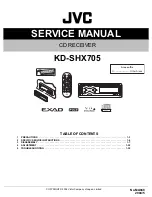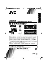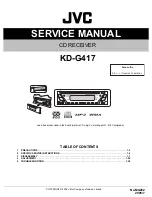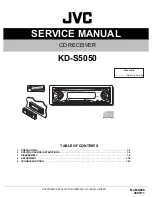


SERVICE MANUAL
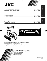
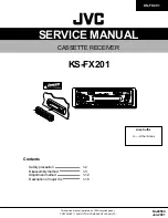
CASSETTE RECEIVER
No.49589
Jan. 2001
COPYRIGHT 2001 VICTOR COMPANY OF JAPAN, LTD.
KS-FX201
KS-FX201
Area Suffix
U ---- Other Areas
Contents
Safety precaution
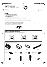
Disassembly method
Adjustment method
Description of major ICs
1-2
1-3
1-12
1-16
This service manual is printed on 100% recycled paper.