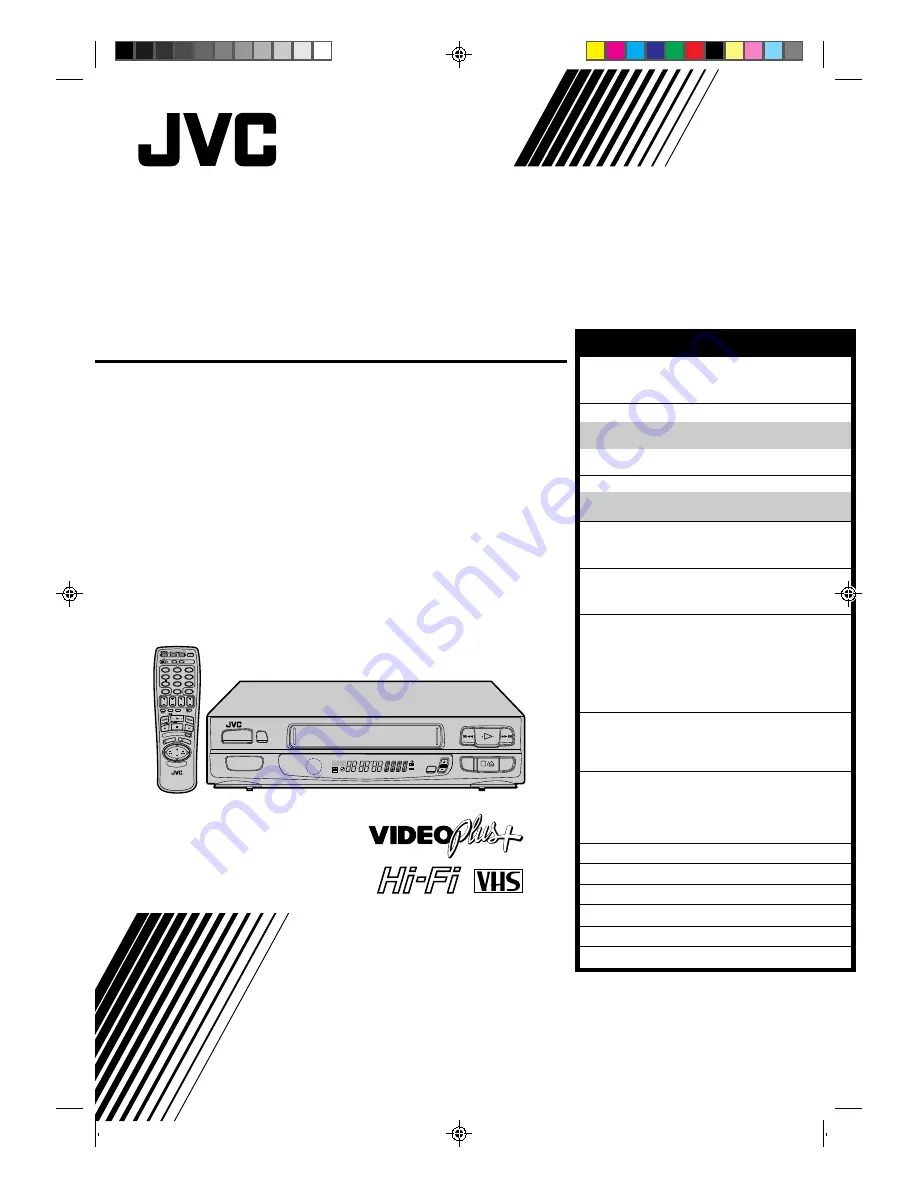
background image

HR-A630EK
HR-A631EK

VIDEO CASSETTE RECORDER

INSTRUCTIONS

PU30425-1799

TM

PAL

q

6

SP 
LP
EP

M

D

D

I T R

W

L R

NORM

TV PROG

SP/LP

TIMER

OPERATE

PROG CHE

CK

TV VOL.

OPERATE

CLOCK

CH SET

DISPLAY

DAILY

AUX

ADD TIME

C.RESET

CANCEL

DATE

STOP

START

AUDIO MONITOR

(MONITOR)

TV/VIDEO

TV

VCR

TIMER

WEEKLY

A

1

2

4

5

3

6

8

0

7

9

B

PUSH JOG

TV

PROG.

PRO

G

OK

EXPRESS PROGRAMMING

STORE

2

1

3

SAFETY FIRST

2

Safety Precautions .................................... 2
Some Do’s And Dont’s ............................. 3

INSTALLING YOUR NEW RECORDER

4

Basic Connections ................................... 4
Tune The TV To Your Video Recorder ...... 5
Connection To A Satellite Receiver .......... 6
Connection To A Stereo System ............... 7

INITIAL SETTINGS

8

Tuner Set .................................................. 8
Clock Set ................................................. 9

PLAYBACK

11

Basic Playback ....................................... 11
Playback Features .................................. 12

RECORDING

17

Basic Recording ..................................... 17
Recording Features ................................ 18

TIMER RECORDING

20

Information On Video Plus+ .................. 20

Guide Channel Set .............................. 20

Video Plus+ Timer Recording ................. 22
Regular Timer Programming .................. 24

Check And Cancel Programmes .......... 26
PDC Recording ................................... 26

EDITING

27

Edit To Or From Another Video
Recorder ................................................ 27
Edit From A Camcorder ......................... 28

USING THE CONFIRMATION DISPLAY

29

Storing Channels Manually .................... 29
Delete A Channel .................................. 30
Change Station Preset Position ............... 30
Set Stations ............................................ 31

TV STATION AND ID LIST

33

TV STATION CHANNEL NUMBER GUIDE

34

TROUBLESHOOTING

35

QUESTIONS AND ANSWERS

37

INDEX

38

SPECIFICATIONS

43

The recorder illustrations appearing in this
instruction manual are of the HR-A630EK.

CONTENTS

Summary of Contents for HR-A630EK

Page 1: ...ereo System 7 INITIAL SETTINGS 8 Tuner Set 8 Clock Set 9 PLAYBACK 11 Basic Playback 11 Playback Features 12 RECORDING 17 Basic Recording 17 Recording Features 18 TIMER RECORDING 20 Information On Video Plus 20 Guide Channel Set 20 Video Plus Timer Recording 22 Regular Timer Programming 24 Check And Cancel Programmes 26 PDC Recording 26 EDITING 27 Edit To Or From Another Video Recorder 27 Edit From...

Page 2: ...t switches operating current on and off IMPORTANT Connection to the mains supply in the United Kingdom DO NOT cut off the mains plug from this equipment If the plug fitted is not suitable for the power points in your home or the cable is too short to reach a power point then obtain a proper safety approved extension lead adapter or consult your dealer BE SURE to replace the fuse only with an ident...

Page 3: ...or has a standby mode Switch off using the switch on the equipment and make sure that your family knows how to do this Special arrangements may need to be made for infirm or handicapped people DON T use equipment such as personal stereos or radios so that you are distracted from the requirements of road safety It is illegal to watch television whilst driving DON T listen to headphones at high volu...

Page 4: ...recorder c Connect the provided RF cable between the RF OUT jack on the rear panel of the recorder and the TV s aerial terminal Before operating the recorder make sure the TV s preset is set to the VIDEO preset AV CONNECTION To Connect To A TV With AV Input Terminals a Connect the aerial recorder and TV as per RF CONNECTION b Connect an optional SCART cable between the AV1 IN OUT socket on the rea...

Page 5: ...e Your TV should be set to the preset designated for use with a video recorder or to a spare preset if there is not a specified video preset on your TV RESET OUTPUT MODE 4 Return the RF OUT switch to ON NOTE If some interference noise is continually seen on the screen consult your JVC dealer The video recorder sends picture and sound signals via the RF connecting cable to your TV on UHF channel 36...

Page 6: ...allows simple connection to a satellite receiver NOTES When connecting your recorder to a TV equipped with 21 pin SCART connectors follow the illustration above using the cables shown in gray For details check your satellite receiver s instruction manual Outdoor Unit Satellite Cable Satellite Receiver Unit TV Aerial cable Aerial Mains outlet Back of TV 21 pin SCART connectors ANT IN RF OUT Aerial ...

Page 7: ...tereo system turn the TV s volume down completely CAUTIONS This recorder has a dynamic range of more than 80 dB with regards to its Hi Fi audio capability It is recommended that you check the maximum level if you are going to listen to the Hi Fi audio signals through a stereo amplifier A sudden surge in the input level to the speakers may damage them Some speakers and televisions are specially shi...

Page 8: ... blinks on the front display panel ACCESS CONFIRMATION DISPLAY 4 The preset position channel and station name ID Z pg 33 of the stations located by your recorder appear in a Confirmation display Confirm all the stored stations by using PUSH JOG fi RETURN TO NORMAL DISPLAY 5 Press CH SET Using the Confirmation display you can skip or add preset positions enter station names and perform other operat...

Page 9: ... you turn off Just Clock off the accuracy of your recorder s built in clock may be reduced which could adversely effect timer recording Both Auto and Manual clock setting procedures begin from step 3 1 2 4 5 3 6 8 0 7 9 1 3 2 OK 2 4 1 Just Clock Preset Position CONTINUED ON NEXT PAGE SET CLOCK AUTOMATICALLY 3 At the Clock Set display press PUSH JOG The Clock Set display blinks and clock setting be...

Page 10: ...d automatically and the day digits begin blinking Input the correct data If in step 3 of the Manual clock setting procedure the year digits are automatically cleared and the day digits begin blinking it is possible that you have input 29th February for a non leap year Input the correct data SET DATE AND TIME 3 Press PUSH JOG fi to set the hour then press OK The minutes display begins blinking Repe...

Page 11: ...utomatically FIND PROGRAMME START POINT 2 If the tape is advanced past the start point press REW To go forward press FF START PLAYBACK 3 Press PLAY STOP PLAYBACK 4 Press STOP on the remote or STOP EJECT on the recorder s front panel Then press STOP EJECT to remove the cassette Usable cassettes Compact VHS camcorder recordings can be played on this video recorder Simply place the recorded cassette ...

Page 12: ...l picture OR During still picture press and hold PUSH JOG or Release to return to still picture To resume normal playback press PLAY fi Variable Speed Search ACTIVATE VARIABLE SPEED SEARCH 1 During playback press PUSH JOG or The more times you press the faster the playback picture moves To decrease speed press the button for the opposite direction To resume normal playback press PLAY fi High Speed...

Page 13: ...gins playback of the last timer recorded programme If you have several programmes recorded you can easily access any of them NOTE Before starting make sure that the recorder is off and that the Timer mode is disengaged ACTIVATE INSTANT REVIEW 1 Press REVIEW The recorder power comes on and the recorder searches for the index code indicating the start of the last timer recorded programme Once it s f...

Page 14: ...nning of B from the current position press PUSH JOG twice To locate the beginning of D from the current position press PUSH JOG once When the specified index code is located playback begins automatically Current position Index number fi fi fi A B C D E F 2 1 1 2 3 Repeat Playback Your video recorder can automatically play back the whole tape 20 times repeatedly START PLAYBACK 1 Press PLAY ACTIVATE...

Page 15: ...ng on the type of TV the top and bottom portions of superimposed displays may be cut off during NTSC playback 1 2 4 5 3 6 8 0 7 9 1 3 2 AUDIO MONITOR Soundtrack Selection Your video recorder is capable of recording three soundtracks HI FI L HI FI R and NORM and will play back the one you select During Playback Pressing AUDIO MONITOR on the remote control changes the soundtrack being played back as...

Page 16: ...OWER SUPPLY 1 Unplug the mains power cord from the mains outlet SET A B CODE SWITCH 2 Set to B RE SUPPLY POWER 3 Plug the mains power cord back into the mains outlet TURN THE RECORDER ON 4 Press OPERATE on the remote control The recorder will now only respond to B code signals NOTE Some TV sets may malfunction in response to the B mode If this happens switch back to the A mode PLAYBACK cont Next F...

Page 17: ...r 5 seconds followed by the preset position number Only stations that appear in the Confirmation display will be displayed SET TAPE SPEED 3 Press SP LP Check the SP LP indicator on the recorder display panel to confirm the selected tape speed START RECORDING 4 Press and hold RECORD and PLAY on the remote control or press RECORD on the recorder PAUSE RESUME RECORDING 5 Press PAUSE Press PLAY to res...

Page 18: ...reo and bilingual broadcasts The NICAM audio programme will be recorded on the Hi Fi audio track and the Standard audio programme on the Normal audio track To listen to a stereo programme press AUDIO MONITOR until L and R appear on the front panel To listen to a bilingual programme press AUDIO MONITOR until either L or R appears on the front panel as required To listen to the Standard audio progra...

Page 19: ...nutes press RECORD to extend the time Each press extends recording time by 30 minutes NOTE You can only perform ITR using the RECORD button on the recorder s front panel Elapsed Recording Time Indication You can check the exact time of a recording SET COUNTER DISPLAY 1 Press DISPLAY so that a counter reading appears on the dispay panel If you press DISPLAY again clock display appears RESET COUNTER...

Page 20: ...edure on page 9 After setting the Guide Channel the station names and preset positions may be incorrect if you stored or skipped channels In this case re perform Guide Channel setting q 6 1 2 4 5 3 6 8 0 7 9 1 3 2 OK NUMBER CH SET CANCEL Guide Channel Preset Position TV PROG MAKE LIST OF STORED PRESET POSITIONS AND STATION NAMES 1 Ex ACCESS CH SET DISPLAY 2 Press and hold CH SET for over 2 seconds...

Page 21: ...n the front display for a few seconds Input the correct PlusCode number Repeat steps 4 and 5 as necessary RETURN TO NORMAL DISPLAY 6 Press CH SET and selection is complete If you already know the Guide Channel number for a station 1 After step 3 press PUSH JOG The Guide Channel number begins blinking 2 Enter the Guide Channel number using the NUMBER keys or PUSH JOG fi then press PUSH JOG The Pres...

Page 22: ...CODE NUMBER 2 Press the NUMBER keys to enter the PlusCode number of a programme you wish to record If you make a mistake press CANCEL and then input the correct number ACCESS PROGRAMME DISPLAY 3 Press OK and the Programme display appears Press PROG CHECK to confirm the date and the Preset position If the number you entered is invalid Err or appears Press CANCEL and input a valid PlusCode number If...

Page 23: ...To Timer Record Weekly Or Daily Serials after pressing OK in step 3 press WEEKLY NUMBER key 9 for weekly serials or DAILY NUMBER key 8 for daily serials Monday Friday W or D appears on the front display panel You can programme this recorder to timer record as many as 8 programmes If you try to programme the recorder to record a ninth FULL appears on the front display panel To record the extra prog...

Page 24: ...E DISPLAY 2 Press START If you re not receiving PDC Programme Delivery Control press NUMBER key 7 to set to OFF so that the indicator disappears Z pg 26 ENTER PROGRAMME START TIME 3 Press START to enter the time you want recording to start Press and hold START to move in 30 minute increments or press and release repeatedly to move 1 minute at a time ENTER PROGRAMME STOP TIME 4 Press STOP to enter ...

Page 25: ...er disables all other functions while in the Timer mode If you want to use the recorder but its Timer mode is engaged press TIMER and all other functions are operable To re engage the timer press TIMER You can programme this recorder to timer record as many as 8 programmes If you try to programme the recorder to record a ninth FULL appears on the front display panel To record the extra programme y...

Page 26: ...stations PDC Programme Delivery Control is a service designed to assure safe accurate timer recording With this system special code signals are transmitted together with the audio video signals These code signals control your video recorder and have precedence over advertised times you preset in the timer This means that your recorder will start and stop recording when the preset TV programmes act...

Page 27: ...NG DECK S INPUT MODE 2 Set to AUX With this video recorder press NUMBER key 0 and or TV PROG to select depending on the connector being used AU 1 for the AV1 IN OUT connector or AU 2 for the AV2 IN connector START SOURCE PLAYER 3 Engage its Play mode START RECORDING DECK 4 Engage its Record mode NOTE All necessary cables can be obtained from your dealer 1 2 4 5 3 6 8 0 7 9 1 3 2 TV Receiver Player...

Page 28: ...connectors SET RECORDER S INPUT MODE 2 If you re using the AV1 IN OUT connector select AU1 by pressing NUMBER key 0 and or TV PROG If you re using the AV2 IN connector select AU2 by pressing NUMBER key 0 or TV PROG START CAMCORDER 3 Engage its Play mode START RECORDER 4 Engage its Record mode 1 2 4 5 3 6 8 0 7 9 1 3 2 Your recorder Recorder Player NUMBER 0 TV PROG Cable adapter Camcorder Audio Vid...

Page 29: ...osition in which you want to store a channel is displayed then press OK The Manual Ch Set display appears INPUT CHANNEL 4 The channel number 21 appears blinking Press the NUMBER keys to input the channel number you want to store For fine tuning adjustment press PUSH JOG until the channel number blinks then press PUSH JOG fi While tuning or appears ENTER NEW CHANNEL INFORMATION 5 Press OK or STORE ...

Page 30: ... and 2 as necessary RETURN TO NORMAL DISPLAY 3 Press CH SET Delete A Channel Change Station Preset Position SELECT ITEM 1 Press PUSH JOG fi until the item you want to move is displayed Then press OK and the station name or and its channel number begin blinking SELECT NEW POSITION 2 Press PUSH JOG fi to move the station to the new preset position then press OK Example If you moved the station in po...

Page 31: ...y RETURN TO NORMAL DISPLAY 4 Press CH SET NOTE First perform step 1 of the above procedure SELECT STATION NAME CHARACTER 2 Press PUSH JOG and the first letter of the station name or begins blinking ENTER NEW CHARACTER 3 Press PUSH JOG fi to cycle through the characters A Z 0 9 space and stop when the desired one is indicated then press PUSH JOG to enter Enter the remaining characters the same way ...

Page 32: ...d SELECT CHANNEL TO FINE TUNE 1 Press PUSH JOG fi until the channel you want to tune is displayed ACCESS MANUAL CH SET DISPLAY 2 Press OK three times The Manual Ch Set display appears PERFORM TUNING 3 Press PUSH JOG fi until the picture is its clearest Then press OK The Confirmation display appears Repeat steps 1 through 3 as necessary RETURN TO NORMAL DISPLAY 4 Press CH SET CH SET PUSH JOG ...

Page 33: ... ORF1 ORF1 ORF2 ORF2 ORF3 ORF3 OWL 3 OWL3 Premiere PRM1 PR07 PR07 RAI1 RAI1 RAI2 RAI2 RAI3 RAI3 RB1 RB1 RB3 RB3 Rikisutvarpid S RKPS RTBF 1 RTB1 RTBF 2 RTB2 STATION NAME ID RTE 1 RTE1 RTL RTL RTL 2 RTL2 RTP RTP SAT SAT 1 SAT1 Scottish TV SCOT SC4 SC4 SDR SDR SDR1 SDR1 SFB1 SFB1 SFB3 SFB3 SKY Sky One SKY1 Sky Net SKYN Sport SPRT SR 1 SR1 Super RTL SRTL STV Test STVT STV 1 STV1 STV 2 STV2 Suedwest3 ...

Page 34: ...ge Hill 22 28 25 32 Sutton Coldfield 46 40 43 50 The Wrekin 26 33 23 29 Waltham 58 64 61 54 North Belmont 22 28 25 32 Emley Moor 44 51 47 41 BBC1 BBC2 ITV CH4 North West Caldbeck 30 34 28 32 Winter Hill 55 62 59 65 North East Bilsdale West Moor 33 26 29 23 Chatton 39 45 49 42 Pontop Pike 58 64 61 54 Scotland Angus 57 63 60 53 Black Hill 40 46 43 50 Sandale 22 Caldbeck 34 28 32 Creigkelly 31 27 24 ...

Page 35: ...le TV broadcasts are clear PLAYBACK POSSIBLE CAUSE If you re using the RF OUT connec tion the TV receiver s preset selector is set to the wrong video preset the RF switch has been mistak enly set to OFF If you re using the AV connection the TV receiver is not set to the AV mode This is normal The automatic tracking mode is engaged The automatic tracking mode is engaged Automatic tracking is engage...

Page 36: ...stop blinking 4 blinks for 10 seconds and the Timer mode is disengaged 5 The cassette is automatically ejected the power shuts off and and won t stop blinking 6 Video Plus does not timer record properly POSSIBLE CAUSE The clock and or the timer have been set incorrectly The timer is not engaged The timer is engaged but there s no cassette loaded The loaded cassette has had its Record Safety tab re...

Page 37: ...codes too close together RECORDING Q When I pause and then resume a recording the end of the recording before the pause is overlapped by the beginning of the continuation of recording Why does this happen A This is normal It reduces distortion at the pause and resume points Q Can the video recorder indefinitely remain in the Record Pause mode A No The video recorder shuts off automatically after 5...

Page 38: ...9 G Guide Channel Z pg 20 H Head Cleaning Z pg 2 High Seed Search Z pg 12 I Index Code Z pg 14 Index Search Z pg 14 Instant ReView Z pg 13 Instant Timer Recording ITR Z pg 19 J Just Clock Z pg 9 L Load A Cassette Z pg 11 M Manual Channel Set Z pg 29 Manual Clock Set Z pg 10 Manual Tracking Z pg 13 Moisture Condensation Z pg 2 N Next Function Memory Z pg 16 NICAM Z pg 18 NTSC Playback Z pg 15 P Pro...

Page 39: ...ard search Z pg 11 7 Infrared Beam Receiving Window is where remote control should be aimed when in use 8 Display Panel provides clear view of various displays and indicators Z pg 42 9 SP LP Button selects tape speed Z pg 17 0 TV PROG Buttons select preset Z pg 8 RECORD Button starts regular recording press once Z pg 17 Instant Timer Recording press twice sets duration of ITR Z pg 19 STOP EJECT Bu...

Page 40: ...on erases previously entered data Z pg 21 C RESET Button resets counter to 0 00 00 Z pg 19 8 START Button accesses Program display inputs of programme Start Time Z pg 24 9 STOP Button inputs programme Stop Time Z pg 24 0 SP LP Button selects tape speed Z pg 17 Digit Entry Button is used in controlling con nected TV Z pg 41 AUDIO MONITOR Button changes output sound mode Z pg 15 TV Mute Button mutes...

Page 41: ... TV VOL fi Button controls volume of con nected TV Z Operating JVC TVs in the right column Installing Batteries 1 Open the battery compartment cover 2 Insert 2 R6 size batteries provided in the correct directions 3 Replace the cover How To Use The remote control can operate most of your video recorder s functions as well as basic functions of JVC TV sets See below Point the remote control toward t...

Page 42: ...nt time Z pg 9 Counter and Clock Display appear alternately when DISPLAY is pressed Channel Display shows station name being received and its preset position Mode shows external input mode selected Audio Mode Indicator displays audio output mode currently selected Z pg 15 DISPLAY PANEL SP LP EP M D D I T R W NORM L R 7 0 8 1 2 3 5 4 9 6 5 ANT IN Connector enables connection of aerial Z pg 4 6 RF O...

Page 43: ...l scan system Signal to noise ratio 45 dB Horizontal resolution 250 lines Frequency range 70 Hz to 10 000 Hz Normal audio 20 Hz to 20 000 Hz Hi Fi audio Input Output 21 pin scart connector x 2 IN OUT x 1 IN x 1 RCA connector x 1 OUT x 1 TUNER TIMER TV channel storage capacity 99 positions AUX position AU Tuning system Frequency synthesized tuner Channel coverage UHF channels 21 69 470 862 MHz Aeri...

Page 44: ...HR A630EK A631EK COPYRIGHT 1996 VICTOR COMPANY OF JAPAN LTD EK Printed in Japan 0496HOV UN VP VICTOR COMPANY OF JAPAN LIMITED ...

Reviews: