background image

INTRODUCTION

CONTROLS,
INDICATORS AND
CONNECTORS

PREPARATIONS

PREPARATIONS
FOR OPERATION

SETTING AND 
ADJUSTMENTS 
BEFORE SHOOTING

SHOOTING
OPERATION

PLAYBACK MODE

USING EXTERNAL
COMPONENTS

MENU SCREENS

FEATURES OF THE 
CAMERA SECTION

OTHERS

HD CAMERA RECORDER

INSTRUCTIONS

GY-HD200U/CHU

GY-HD200E/CHE

GY-HD201E/CHE

Thank you for purchasing this JVC product. Before operating this
device, please read the instructions carefully to ensure the best
possible performance.

For Customer Use:

Enter below the Serial No. which is located on the body.
Retain this information for future reference.
Model No. 
Serial No.

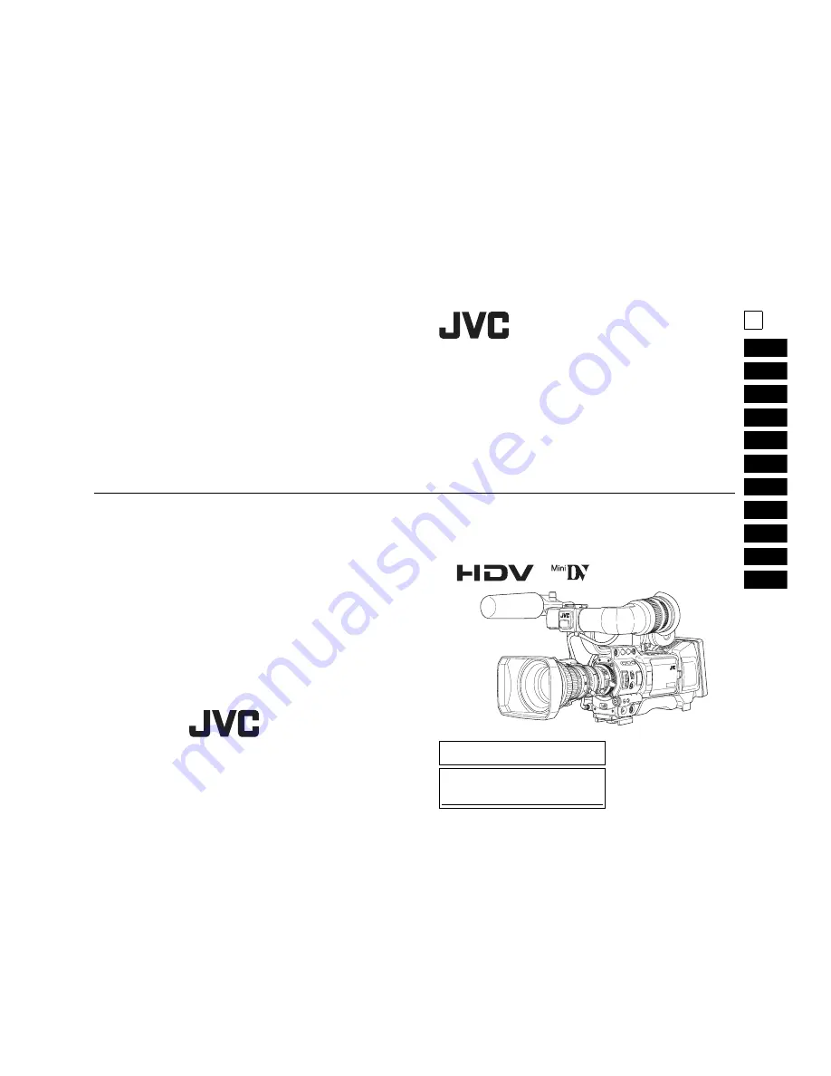
* The illustration shows the GY-HD200U/

GY-HD200E/GY-HD201E HD CAMERA
RECORDER with the provided lens,
viewfinder and microphone  attached.

LST0512-001A

E

LST0512-001A

© 2006 Victor Company of Japan, Limited

LST0512-001A

Summary of Contents for GY-HD200CHE

Page 1: ...01E CHE Thank you for purchasing this JVC product Before operating this device please read the instructions carefully to ensure the best possible performance For Customer Use Enter below the Serial No which is located on the body Retain this information for future reference Model No Serial No The illustration shows the GY HD200U GY HD200E GY HD201E HD CAMERA RECORDER with the provided lens viewfin...

Page 2: ...les These limits are designed to provide reasonable protection against harmful interference in a residential installation This equipment generates uses and can radiate radio frequency energy and if not installed and used in accordance with the instructions may cause harmful interference to radio communi cations However there is no guarantee that interference will not occur in a particular installa...

Page 3: ...t No user ser viceable parts inside Refer servicing to qualified service person nel Due to design modifications data given in this instruction book are subject to possible change without prior notice The apparatus shall not be exposed to dripping or splashing and that no objects filled with liquids such as vases shall be placed close to the apparatus Worded CAUTION Danger of explosion if battery i...

Page 4: ... 24p mode shooting function In HDV format it records in 24p mode It uses a 2 3 2 3 pulldown when recording to tape and con verts the images to 60 frames Component output is con verted to 60 frames during playback as well 24p DV format video uses a 2 3 2 3 pulldown 24p Mode A 2 3 3 2 pulldown 24p Advanced Mode is also supported It can shoot with the same number of frames as movie film Tapes recorde...

Page 5: ...ing Time Codes in Continuation of Time Codes Recorded on Tape 47 Playing Back Time Code 47 Synchronizing with the Time Code of the IEEE1394 DV Connected Master Unit 48 Screen Adjustment 49 Viewfinder Adjustment 49 Back Focus Adjustment 50 White Balance Adjustment 51 White Balance Adjustment 51 Full Auto White Balance FAW 51 White Shading Adjustment 52 SETTING AND ADJUSTMENTS BEFORE SHOOTING Settin...

Page 6: ...is may result in personal injury or dam age to the mechanism To prevent damage to the connectors use this device with the connector covers on when you are not using the video audio signal output connectors CAUTION Do not point the lens or viewfinder directly at the sun or other strong light source Eye damage could result If the lens or viewfinder is left pointed at the sun rays may collect inside ...

Page 7: ...condensation dew When this occurs the head drum and tape guides are covered with droplets allowing the tape to be stuck to them leading to tape dam age Condensation occurs in the following cases When this device is suddenly moved from a cold place to a warm place When a room heater has just started or when this device is exposed directly to cold air from an air conditioner When this device is plac...

Page 8: ...ocus knob for the macro ring After the required operation be sure to return the macro focusing ring to the normal position X See Attaching the Zoom Lens on page 33 X See Back Focus Adjustment on page 50 M RET W T A MACRO 3 2 4 5 6 7 8 9 1 0 a b c d A Activates the auto iris feature M Allows manual iris control S Servo zoom mode Allows operation by the zoom servo control lever 6 M Manual zoom mode ...

Page 9: ... viewfinder This switch works when the TC UB item on the LCD VF 3 4 menu screen is set to ON 4 TC GENE Time code generator setting switch Switch for setting the time code generator to preset mode or regeneration mode It is also used to select the time code run mode when the preset mode is selected MEMO Preset of time code and user s bits is performed on the TC UB CLOCK menu X See page 44 X See TC ...

Page 10: ... changes each time the but ton is pressed X See Status Screens on page 22 Pressing this button for more than 1 second in the nor mal screen mode displays the menu screen in the view finder or on the LCD monitor Pressing this button while the menu screen is displayed in the viewfinder or on the LCD monitor makes the menu screen disappear X See Setting Menu Screens on page 72 b GAIN Sensitivity sele...

Page 11: ...n the Camera mode Outputs the playback audio signal in the VTR mode When a HDV DV signal IEEE1394 is input the EE sound of the input audio signal is output in the VTR mode HDV DV signal input is possible with the GYHD200U GY HD201E MEMO Alarm sound is not output 0 IEEE1394 IEEE1394 connector 6 pin Using an IEEE1394 cable optional a digital video com ponent with IEEE1394 connector can be connected ...

Page 12: ...CD screen and the viewfinder screen When LCD VF in the LCD VF 4 4 menu display is set to ON press the DISPLAY button for 2 seconds to switch the LCD screen ON and OFF Press the DIS PLAY button briefly to change the display mode for the LCD screen as follows X See Magnified Status Indications on the LCD Monitor on page 29 f VTR VTR indicator This indicator lights when the camera is in the VTR mode ...

Page 13: ...94 Out Component Out Composite Out ON 60 30 N A N A 1080 60i 480 60i 50 25 N A N A 1080 50i 576 50i Playback IEEE1394 Out Component Out Composite Out HDV PB OUTPUT menu item NATIVE 720P 1080I NTSC PAL HDV 720 60p q q q 1080 60i 480 60i N A 480 60i 720 30p q 720 60p q 1080 60i 480 60i N A 480 60i 720 50p q q q 1080 50i N A 576 50i 576 50i 720 25p q 720 50p q 1080 50i N A 576 50i 576 50i 720 24p q 7...

Page 14: ...tter Speed is changed manually the setting condition is displayed for about 3 seconds at the time the change is made Set the shutter display method to seconds or angle in SHUTTER DISP on the LCD VF 3 4 menu screen Only when frame rate is 24p or 25p mode 266S DD STATUS 0 Screen 1 2 3 9 8 7 6 5 4 0 Setting Status Contents of Indications Gain value was changed GAIN 0 dB 3 dB 6 dB 9 dB 12 dB 15 dB 18 ...

Page 15: ...ion operations FOCUS Displayed when the Focus Assist function is ON SKIN AREA Blinks while the skin detail color area is displayed ALC Displayed when ALC function alone is ON FAS Displayed when the Full Auto Shooting function is ON S Displayed when the shutter speed is a setting other than the default setting X See page 83 0 Indication of DR HD100 Oper ation When a DR HD100 HDD unit by FOCUS enhan...

Page 16: ...n the LCD VF 3 4 menu screen is set to DEG the shutter display for the frame rate in 24p or 25p mode is degrees STATUS 3 Displays a list of setting statuses for USER1 2 and 3 as well as LENS RET item on the SWITCH MODE menu screen X See page 83 Events are not displayed while these statuses are being displayed STATUS 4 This screen only displays VTR mode indication date and time event display and al...

Page 17: ... editing software SLOW 1 About 0 1 speed SLOW 2 About 0 2 speed SLOW 3 About 0 5 speed 29 Magnified Status Indications on the LCD Monitor The characters on the status screens can be showed alone in magnified size on the LCD monitor 1 Set the LCD VF item on the LCD VF 4 4 menu screen to ON X See page 89 2 When the DISPLAY button is briefly pressed while the LCD monitor is displayed the displayed co...

Page 18: ...FF ON OFF ON OFF ON REC ASPECT Cannot be selected DV 60I DV 50I DV 24P DV 24PA DV 25P 4 3 16 9 HDV HD60P HDV HD50P HDV HD30P HDV HD25P HDV HD24P 16 9 31 Switching between the LCD Screen and Viewfinder Display When the LCD VF item in the LCD VF 4 4 menu is set to OFF the LCD monitor and viewfinder VF displays are as shown below MEMO You can switch between the LCD monitor and the view finder by hold...

Page 19: ... the Zoom Lens 1 Loosen the mount ring 2 Attach the lens with its pin aligned with the hole in the mount 3 Tighten the mount ring 4 Connect the cable connector 5 Clamp the lens cable CAUTION Be sure to tighten the mount ring completely Incomplete tightening may result in the lens dropping off or disturbed back focus Set this device s power switch to OFF before the zoom lens is attached or detached...

Page 20: ...d Set the switch on the side of the SD memory card to the LOCK position MEMO SDHC compliant memory cards cannot be used with this device Core filter black SD memory card cover Cutout LOCK switch 35 Attaching the Tripod Base Optional Use the optional tripod base to place the camera on a tripod 1 Attach the tripod base on the tripod by using the hole that balances this device most optimally 2 While ...

Page 21: ...C adapter to this device and an AC outlet or mount a charged battery on this device 2 Set the POWER switch on this device to ON or OFF charging takes places with the POWER switch set to either of the positions 3 Leave the equipment in this condition for about 4 hours The built in battery will remain charged for about 3 months after being charged for about 4 hours IEEE 1394 C H 2 A U D I O O U T C ...

Page 22: ...t in reduced battery capacity If the battery capacity is reduced by repeating incomplete recharging or recharging without discharging once dis charge the battery pack completely then recharge it to restore the battery capacity If the battery pack is recharged with its internal tempera ture raised immediately after use recharging may not be performed completely Perform charging in an environment wh...

Page 23: ... Camera Record standby mode STOP mode REC INHIBIT is displayed on the LCD monitor and in the viewfinder VTR STOP mode REC SAVE switch Tape window EJECT switch Cassette holder Videocassette cover Inner cover 41 Setting and Displaying the Date and Time The date and time of the built in clock should be set Pow ered by the built in backup battery the set date and time data continue to count even when ...

Page 24: ...e displayed In VTR playback mode The date and time recorded on the tape are displayed In VTR stop mode The last read date and time values are displayed When an HDV DV sig nal is input from the IEEE1394 connector The date and time of the DV input are displayed in DV format The date and time of the internal clock are displayed in HDV format GY HD200U GY HD201E only Date Time 43 Displaying Time Code ...

Page 25: ...etting time code data The time code and user s bit data are preset on the TC UB CLOCK menu screen 1 Display the TC UB CLOCK menu screen Select the TC UB CLOCK item on the TOP MENU screen 2 Set the time code hours minutes seconds frames 1Rotate the SHUTTER dial to align the cursor K with TC PRESET and then press the SHUTTER dial The first digit of the time code blinks The blinking digit is the one ...

Page 26: ...N Preset operation is terminated in the following TC DISPLAY switch is changed CAM VTR mode switch is changed VTR operations are performed USER1 USER2 and USER3 presetting in the SWITCH MODE menus screen is not available when the Time Code Preset screen is displayed The time code preset screen is displayed on the LCD screen or viewfinder It will not be output from the VIDEO OUT terminal USER 3 USE...

Page 27: ...N DROP is not synchronized it will not run properly Synchronize DROP NON DROP before using MACRO USER 3 USER 2 USER 1 STATUS MENU 2 1 ND FILTER REC OFF ON POWER WHT BAL AUTO AUDIO LEVEL AUTO CH 1 CH 2 VF BRIGHT MACRO USER 3 USER 2 USER 1 STATUS MENU 2 1 ND FILTER REC OFF ON POWER WHT BAL AUTO AUDIO LEVEL AUTO CH 1 CH 2 VF BRIGHT Master unit Slave unit IEEE1394 cable IEEE1394 terminal IEEE1394 term...

Page 28: ...orrect white balance is obtained the approximate color temperature is displayed together with AUTO WHITE A B OK for about 5 seconds MEMO Fine tune red and blue to match the white adjusted in white balance in WHITE PAINT R B on the WHITE BAL ANCE menu screen X See page 82 Error messages If the adjustment ends abnormally an error message as described below blinks for about 5 seconds NG OBJECT Improp...

Page 29: ... R LEVEL G and LEVEL B with the SHUTTER dial while referring to the monitor When setting values are increased colors at the bottom of the screen are suppressed and the top is enhanced LEVEL R Adjusts reds LEVEL G Adjusts greens LEVEL B Adjusts blues Range 128 to 127 5 Press the SHUTTER dial after changing the setting val ues to save in the memory 6 Press the STATUS button to return to the normal s...

Page 30: ... 2 Selecting the CH 2 channel input connector Select using the CH 2 INPUT switch MEMO The audio from the INPUT1 connector is also input into CH 1 regardless of the setting Selecting the audio signal input Select the sound to be input to the INPUT1 or INPUT2 con nector using the AUDIO INPUT switch The setting is made for each of INPUT1 or INPUT2 connector CAUTION When connecting a component that do...

Page 31: ...ion 1 Set the POWER switch to ON This device turns on in camera mode 2 Start recording Press the REC VTR trigger button on this device to start recording Once recording has started the FRONT TALLY lamp and BACK TALLY lamp light red MEMO The way the FRONT TALLY and the BACK TALLY lamps flash differ depending on what you set in the FRONT TALLY and BACK TALLY items on the OTHERS 1 2 menu screen X See...

Page 32: ... records the color bar video and the test tone 1 kHz sine wave of the built in signal generator at the beginning of the tape Then it records the black video signal and the mute audio signal for the duration specified in advance When the recording is completed this device enters the Record Standby mode The time code value at the Record Standby position becomes the time code specified in advance HEA...

Page 33: ... connected to the video output connector MEMO This device can play back the following two types of video cassettes MiniDV videocassette DVCAM videocassette Tapes recorded in the LP mode cannot be played back 1 Set the POWER switch to ON 2 Set this device to the VTR mode Press the CAM VTR button to turn on the VTR indicator Playback is also possible in the Camera mode Playback operation becomes pos...

Page 34: ...nd the after recorded sound on CH 3 and CH 4 simultaneously CH3 4 To reproduce the sound after recorded on CH 3 and CH 4 PB AUDIO CH DV AUDIO OUT connector CH 1 CH 2 CH1 2 CH1 CH2 MIX CH1 CH3 CH2 CH4 CH3 4 CH3 CH4 MONITOR SELECT PB AUDIO CH DV AUDIO MONITOR CH1 2 MIX CH3 4 CH 1 L R CH1 L R CH1 CH3 L R CH3 BOTH MIX STEREO L R CH1 CH2 L CH1 R CH2 L R CH1 CH2 CH3 CH4 L CH1 CH3 R CH2 CH4 L R CH3 CH4 L...

Page 35: ... on the left panel of this device 2 Connect the IEEE1394 cable 3 Turn both devices on 4 Set this device to VTR mode Press the CAM VTR button The VTR indicator lights CAUTION Set the IEEE1394 switch on both devices to either HDV or DV Start recording after making sure that both devices are properly connected 5 Set the PB TAPE item on the VIDEO FORMAT menu screen X See page 76 Select whether to auto...

Page 36: ...his device s camera image and sound can be recorded for backup on another component that is equipped with IEEE1394 connector Connections Use this device as the master unit Connect the master unit and the backup unit with a IEEE1394 cable Settings Master unit this device 1 Set the IEEE1394 switch on left side of this device 2 Place in Camera mode 3 Set the 1394 REC TRIG item on the OTHERS 2 2 menu ...

Page 37: ... or 1 50 with the remote control unit when in 24p mode the shutter speed for the device is 1 48 AUTO WHITE Function When the device is in VTR mode during playback or HEADER REC the AUTO WHITE function does not work even if the auto white operation is performed with the RM LP55 and RM LP57 In the case of the RM LP55 LOW LIGHT ERROR is dis played on the LCD screen of the RM LP55 IEEE 1394 C H 2 A U ...

Page 38: ...on the menu screens differ with the Camera mode and the VTR mode The contents of set items are stored in this device s memory and are retained even when the power is turned off The FILE MANAGE menu screen can be used to store the menu setting contents on this device or SD memory card Camera Mode TOP MENU screen CAM 71 VTR Mode IEEE1394 Input Mode HDV DV signal input is possible with the GY HD200U ...

Page 39: ...is device is in the Camera mode or in the VTR mode In the VTR mode the CAMERA OPERATION CAMERA PROCESS and SWITCH MODE menu screens are not displayed Item Function VIDEO FORMAT Displays the menu screen for setting the video format for shooting and playing back video Camera mode It consists of two screens VTR mode It consists of one screen The cursor K does not move to this item when this device is...

Page 40: ...ing a 720 30p signal HDV HD50P HDV format Shoots using a 720 50p signal 50 25 HDV HD25P HDV format Shoots using a 720 25p signal DV 50I DV format Shoots using a 576 50i signal E model Only DV 25P DV format Shoots using a 576 25p signal E model Only DV 24P DV format Shoots at 480 24p 2 3 2 3 pulldown U model Only 24 DV 24PA DV format Shoots at 480 24p 2 3 3 2 pulldown U model Only HDV HD24P HDV for...

Page 41: ...mera mode 1 REMOTE appears as the setting value of this item when the remote control unit is connected Item Function Setting bold characters indicate initial settings AE LEVEL 1 For adjusting the image level when using auto iris ALC or EEI Increase value Increases level Decrease value Decreases level Settings 3 2 NORMAL 0 2 3 ALC MAX Sets the maximum ALC value to automatically change the signal in...

Page 42: ...RA PROCESS 2 2 Menu Screen 1 REMOTE appears as the setting value of this item when the remote control unit is connected Item Function Setting bold characters indicate initial settings BLACK 1 Changes the gain in dark areas Change this depending on the video signal being shot STRETCH LEVEL The amount of stretching increases from LEVEL1oLEVEL2oLEVEL3oLEVEL4oLEVEL5 Settings LEVEL1 LEVEL2 LEVEL3 LEVEL...

Page 43: ...k and white Item Function Setting bold characters indicate initial settings R GAIN For manually adjusting the shading of the R axis of the color matrix red and cyan Increase the number Enhances red and cyan Decrease the number Reduces red and cyan Settings MIN 5 4 NORMAL 0 4 MAX 5 R ROTATION For manually adjusting the color phase of the R axis of the color matrix red and cyan Increase the number I...

Page 44: ...is only displayed in camera mode Item Function Setting bold characters indicate initial settings SHUTTER Sets the fixed value STEP for values that can change using the SHUTTER dial on the right panel or the VARIABLE used when shooting computer monitors STEP Switches the shutter speed using fixed values VARIABLE Set when shooting a computer monitor etc You can set the following using the REC item o...

Page 45: ...s with a 16 bit 48 kHz sampling frequency If the DV format is 12 bit 32 kHz up to 4 recording track channels are available Of those this device records on the CH 1 and CH 2 channels This device is not capable of dubbing AUDIO LIMITER Sets whether or not AUDIO LIMITER functions when the CH 1 CH 2 AUDIO SELECT switch 2 on page 13 is set to MANU OFF AUDIO LIMITER is turned off ON AUDIO LIMITER is tur...

Page 46: ...at or 24P or 25P mode CENTER MARK 1 Sets whether or not a center mark is displayed when the safety zone is displayed ON Center mark is displayed OFF Center mark is not displayed MEMO When the SAFETY ZONE item is set to OFF is indicated and this item cannot be selected FOCUS ASSIST Sets the FOCUS ASSIST function Press the FOCUS ASSIST button on page 14 6 or page 18 7 to operate the FOCUS ASSIST fun...

Page 47: ...hen remaining battery level becomes less than 12 the display changes to RES When CALIBRATION is required from the battery the display switches between TIME CAPA display 30 sec onds and CAL display 2 seconds repeatedly For CALIBRATION refer to the instruction manual of Anton Bauer Battery Please use the remaining battery level and remaining time as a reference for shooting duration SHUTTER DISP Set...

Page 48: ...B of the IEEE1394 input MEMO In HDV format the UB set in this device is recorded regardless of the setting HEADER REC To make settings related to the HEADER REC function align the cursor with this position and then press the SHUT TER dial X See HEADER REC Menu Screen on page 91 TIME DATE To make settings related to the date and time align the cursor with this position and then press the SHUTTER di...

Page 49: ...g the Date and Time on page 42 PAGE BACK The TC UB CLOCK menu returns when the SHUTTER dial is pressed while the cursor is at this position 93 OTHERS 1 2 Menu Screen The OTHERS menu screen consists of two screens 1 2 screen 2 2 screen Item Function Setting bold characters indicate initial settings ANALOG OUT CHAR Sets whether or not to display characters such as status and menus on the screen for ...

Page 50: ...ce staying in REC PAUSE or divided files MEMO The cursor K does not move to this item when this device is recording BACK SPACE HDV IEEE1394 connection 1394 REC TRIGGER X See page 94 Internal VCR start delay External Recorder or HDD vie IEEE1394 terminal P 1394 Connected and Power ON OFF approx 3 seconds N A SYNCRO See Note 1 SPLIT See Note 2 SERIES N A No connection or Power OFF OFF approx 1 secon...

Page 51: ...d the menu settings to be loaded have different video format settings REBOOT is displayed for 3 seconds this device turns off automati cally and then turns on CAUTION This device cannot load scene files from GY HD100 GY HD110 series devices Execute Complete Error Flashing Error display FILE MANAGE menu screen Reboot display 97 Saving settings Select the STORE FILE item on the FILE MANAGE menu scre...

Page 52: ...ANCED PROCESS menu screen In menu setting procedure TOP MENU screen o CAMERA PROCESS 1 2 o CAMERA PROCESS 2 2 o Select ADVANCED PRO CESS item 2 Turn the SHUTTER dial bring the cursor K to the SKIN COLOR ADJUST item and press the SHUTTER dial The SKIN COLOR ADJUST screen is displayed The entire screen becomes black and white and only the areas recognized by the skin detail function are displayed in...

Page 53: ...finder or LCD screen When COLOR GAIN item on the ADVANCED PRO CESS menu screen is set to OFF only the portion the skin detail function is working is displayed in skin color X See page 80 STATUS 0 SD display ZEBRA switch 101 Outputting Color Bars This device can output three types of color bars depending on the camera settings To output color bars make the following settings 1 Turn the FULL AUTO sw...

Page 54: ...vice cannot record or play back in LP mode NO DV SIGNAL DV signal was not input Set the IEEE1394 switch to DV and input a DV signal NO HDV SIGNAL HDV signal was not input Set the IEEE1394 switch to HDV and input an HDV signal COPY INHIBIT Tried to record a copyguarded signal Cannot record a copyguarded signal REC INHIBIT A tape that cannot be recorded back switch is set to SAVE was inserted Set th...

Page 55: ...URE Capstan rotation error 7202 7203 SUPPLY REEL FAILURE Supply reel rotation error 7302 7303 TAKE UP REEL FAILURE Take up reel rotation error 7305 TAKE UP REEL FAILURE Take up reel rotation error when un loading 8000 EMERGENCY TAPE Tape problem detected TURN POWER OFF TURN BACK ON LATER System error when power is turned on HDV DV LED VTR indicator and TALLY lamp flash Only POWER switch operation ...

Page 56: ...ise appears when playing back a tape recorded on another unit When a tape recorded on another unit is played back or used for recording this phenomenon may occur due to tracking errors The transient section between scenes recorded on other units and those recorded on this device may appear disturbed The front section s audio level control doesn t work Is the CH 1 CH 2 AUDIO SELECT switch set to AU...

Page 57: ...i DV 25p 24 01 10 489 5 Hz HDV HD24p DV 24p Dynamic range 300 or more Video Recording format 720 24p 720 25p 720 30p 720 50p 720 60p U E model 480 24p 480 60i U model 576 25p 576 50i E model Video Format HDV Video signal record ing format HDV720p format 8 bit 19 7 Mbps Compression MPEG 2 video profile level MP H 14 DV Video signal record ing format DV format 8 bit 25 Mbps Compression DV compressio...

Page 58: ...for purchasing this JVC product Before operating this device please read the instructions carefully to ensure the best possible performance For Customer Use Enter below the Serial No which is located on the body Retain this information for future reference Model No Serial No The illustration shows the GY HD250 GY HD251 HD CAMERA RECORDER with the provided lens viewfinder and microphone attached LS...

Page 59: ...ules These limits are designed to provide reasonable protection against harmful interference in a residential installation This equipment generates uses and can radiate radio frequency energy and if not installed and used in accordance with the instructions may cause harmful interference to radio communi cations However there is no guarantee that interference will not occur in a particular install...

Page 60: ...revent electric shock do not open the cabinet No user ser viceable parts inside Refer servicing to qualified service person nel Due to design modifications data given in this instruction book are subject to possible change without prior notice The apparatus shall not be exposed to dripping or splashing and that no objects filled with liquids such as vases shall be placed close to the apparatus Wor...

Page 61: ...ed trademark of Sony Corporation 60 Hz 50 Hz HD or HDTV signals Supports both 60 Hz 50 Hz HD or HDTV signals You can select this in a menu screen Cross convert video output You can output converted video from the video output con nectors You can select this in a menu screen Outputs composite component Y C separate and RGB signals as analog video in DV format Outputs composite and component signals...

Page 62: ...Back Time Code 47 Synchronizing with the Time Code of the IEEE1394 DV Connected Master Unit 48 Synchronizing with an External Time Code Generator 49 Screen Adjustment 50 Viewfinder Adjustment 50 Back Focus Adjustment 51 White Balance Adjustment 52 White Balance Adjustment 52 Full Auto White Balance FAW 52 White Shading Adjustment 53 SETTING AND ADJUSTMENTS BEFORE SHOOTING Setting the Video Format ...

Page 63: ...ay result in personal injury or dam age to the mechanism To prevent damage to the connectors use this device with the connector covers on when you are not using the video audio signal output connectors CAUTION Do not point the lens or viewfinder directly at the sun or other strong light source Eye damage could result If the lens or viewfinder is left pointed at the sun rays may collect inside this...

Page 64: ... adhere to the head drum or tape guides and be cooled into water droplets This phenomenon is referred to as condensation dew When this occurs the head drum and tape guides are covered with droplets allowing the tape to be stuck to them leading to tape dam age Condensation occurs in the following cases When this device is suddenly moved from a cold place to a warm place When a room heater has just ...

Page 65: ... knob for the macro ring After the required operation be sure to return the macro focusing ring to the normal position X See Attaching the Zoom Lens on page 33 X See Back Focus Adjustment on page 51 M RET W T A MACRO 3 2 4 5 6 7 8 9 1 0 a b c d A Activates the auto iris feature M Allows manual iris control S Servo zoom mode Allows operation by the zoom servo control lever 6 M Manual zoom mode Allo...

Page 66: ...ch Switch for setting the time code generator to preset mode or regeneration mode It is also used to select the time code run mode when the preset mode is selected MEMO This switch is enabled when TCG SOURCE on the TC UB CLOCK menu screen is set to INTERNAL Preset of time code and user s bits is performed on the TC UB CLOCK menu X See page 44 X See TC UB CLOCK Menu Screen on page 93 5 CAM VTR Came...

Page 67: ... is pressed X See Status Screens on page 22 Pressing this button for more than 1 second in the nor mal screen mode displays the menu screen in the view finder or on the LCD monitor Pressing this button while the menu screen is displayed in the viewfinder or on the LCD monitor makes the menu screen disappear X See Setting Menu Screens on page 75 b GAIN Sensitivity selector switch Electronically boo...

Page 68: ...in This is the 12V DC power input terminal Connect to the AC adapter When a battery is installed and a cable is connected to this terminal power supply from the battery stops and power is supplied by this terminal c GENLOCK AUX IN GENLOCK AUX IN switch Set according to the signal input in the GENLOCK AUX IN terminal GENLOCK Set to this when inputting external synchroni zation signals AUX IN Set to...

Page 69: ... the LCD VF 4 4 menu display is set to OFF press the DISPLAY button for 2 seconds to switch between the LCD screen and the viewfinder screen When LCD VF in the LCD VF 4 4 menu display is set to ON press the DISPLAY button for 2 seconds to switch the LCD screen ON and OFF Press the DIS PLAY button briefly to change the display mode for the LCD screen as follows X See Magnified Status Indications on...

Page 70: ...Composite Out HDV PB OUTPUT menu item NATIVE 720P 1080I NTSC PAL HDV 720 60p q q q 1080 60i 480 60i N A 480 60i 1 480 60i 1 480 60i 720 30p q 720 60p q 1080 60i 480 60i N A 480 60i 1 480 60i 1 480 60i 720 50p q q q 1080 50i N A 576 50i 576 50i 2 576 50i 2 576 50i 720 25p q 720 50p q 1080 50i N A 576 50i 576 50i 2 576 50i 2 576 50i 720 24p q 720 60p q 1080 60i 480 60i N A 480 60i 1 480 60i 1 480 60...

Page 71: ...When the Gain or Shutter Speed is changed manually the setting condition is displayed for about 3 seconds at the time the change is made Set the shutter display method to seconds or angle in SHUTTER DISP on the LCD VF 3 4 menu screen Only when frame rate is 24p or 25p mode 266S DD STATUS 0 Screen 1 2 3 9 8 7 6 5 4 0 STATUS 0 Screen External Image Input Mode AUX IN D V 6 0 I A U X 266S DD a 0 1 2 3...

Page 72: ...Auto Shooting function is ON S Displayed when the shutter speed is a setting other than the default setting X See page 86 0 Indication of DR HD100 Oper ation When a DR HD100 HDD unit by FOCUS enhancements is connected its operation status is displayed DR HD100 is connected displays white Recording with DR HD100 displays red For details refer to the DR HD100 INSTRUCTION MANUAL a AUX display Display...

Page 73: ...lay is not available while this screen is displayed When SHUTTER DISP on the LCD VF 3 4 menu screen is set to DEG the shutter display for the frame rate in 24p or 25p mode is degrees STATUS 3 Displays a list of setting statuses for USER1 2 and 3 as well as LENS RET item on the SWITCH MODE menu screen X See page 86 Events are not displayed while these statuses are being displayed STATUS 4 This scre...

Page 74: ...atus screens can be showed alone in magnified size on the LCD monitor 1 Set the LCD VF item on the LCD VF 4 4 menu screen to ON X See page 92 2 When the DISPLAY button is briefly pressed while the LCD monitor is displayed the displayed contents change every time the DISPLAY button is pressed MEMO When characters indicating the status are displayed in magnified size on the LCD monitor the viewfinde...

Page 75: ...ON OFF ON OFF ON REC ASPECT Cannot be selected DV 60I DV 50I DV 24P DV 24PA DV 25P 4 3 16 9 HDV HD60P HDV HD50P HDV HD30P HDV HD25P HDV HD24P 16 9 31 Switching between the LCD Screen and Viewfinder Display When the LCD VF item in the LCD VF 4 4 menu is set to OFF the LCD monitor and viewfinder VF displays are as shown below MEMO You can switch between the LCD monitor and the view finder by holding...

Page 76: ...ics GY HD250 Gold Mount GY HD251 V Mount Battery mount Monitor Camera Remote Control Unit RM P210 HD SD Cable BNC Monitor Studio Kit KA HD250 IDX Endura Battery Anton Bauer Battery Charger For GY HD250 33 Attaching the Zoom Lens 1 Loosen the mount ring 2 Attach the lens with its pin aligned with the hole in the mount 3 Tighten the mount ring 4 Connect the cable connector 5 Clamp the lens cable CAU...

Page 77: ... the side of the SD memory card to the LOCK position MEMO SDHC compliant memory cards cannot be used with this device Core filter black SD memory card cover Cutout LOCK switch 35 Attaching the Tripod Base Provided only for U model Use the provided tripod base to place the camera on a tri pod U model only 1 Attach the tripod base on the tripod by using the hole that balances this device most optima...

Page 78: ...uilt in battery 1 Connect the AC adapter to the GY HD250 GY HD251 and an AC outlet or mount a charged battery on the GY HD250 GY HD251 2 Set the POWER switch on the GY HD250 GY HD251 to ON or OFF charging takes places with the POWER switch set to either of the positions 3 Leave the equipment in this condition for about 4 hours The built in battery will remain charged for about 3 months after being...

Page 79: ...reduced battery capacity If the battery capacity is reduced by repeating incomplete recharging or recharging without discharging once dis charge the battery pack completely then recharge it to restore the battery capacity If the battery pack is recharged with its internal tempera ture raised immediately after use recharging may not be performed completely Perform charging in an environment where t...

Page 80: ...cord standby mode STOP mode REC INHIBIT is displayed on the LCD monitor and in the viewfinder VTR STOP mode REC SAVE switch Tape window EJECT switch Cassette holder Videocassette cover Inner cover 41 Setting and Displaying the Date and Time The date and time of the built in clock should be set Pow ered by the built in backup battery the set date and time data continue to count even when the power ...

Page 81: ... HDV format Date Time 43 Displaying Time Code The GY HD250 GY HD251 records SMPTE standard NTSC or EBU standard PAL time codes and user s bits In the play mode or the record mode the reproduced time codes or user s bits are shown on the LCD monitor or in the viewfinder Time code generator data is output from the TC OUT ter minal or HD SD SDI terminal The time codes or user s bits can be shown on t...

Page 82: ...creen FRAME RATE 50 25 45 Presetting time code data The time code and user s bit data are preset on the TC UB CLOCK menu screen 1 Display the TC UB CLOCK menu screen Select the TC UB CLOCK item on the TOP MENU screen 2 Set the time code hours minutes seconds frames 1Rotate the SHUTTER dial to align the cursor K with TC PRESET and then press the SHUTTER dial The first digit of the time code blinks ...

Page 83: ...ing in the SWITCH MODE menus screen is not available when the Time Code Preset screen is displayed The time code preset screen is displayed on the LCD screen or viewfinder It will not be output from the VIDEO OUT terminal USER 3 USER 2 USER 1 STATUS MENU 2 1 ND FILTER REC OFF ON POWER WHT BAL AUTO AUDIO LEVEL AUTO CH 1 CH 2 VF BRIGHT USER 3 USER 2 USER 1 STATUS SHUTTER MENU 2 1 ND FILTER OFF USER ...

Page 84: ...3 USER 2 USER 1 STATUS MENU 2 1 ND FILTER REC OFF ON POWER WHT BAL AUTO AUDIO LEVEL AUTO CH 1 CH 2 VF BRIGHT Master unit Slave unit IEEE1394 cable IEEE1394 terminal IEEE1394 terminal Slide the IEEE1394 switch to the DV side Slide the IEEE1394 switch to the DV side DTCG TC SLAVE LOCK EXECUTE USER1 00 00 00 00 CANCEL USER3 Status display 49 Synchronizing with an Exter nal Time Code Generator Synchro...

Page 85: ...viewfinder screen BLACK WHITE Sets the LCD monitor and viewfinder to black and white display MEMO The screen size of the viewfinder can be changed by selecting the desired size with the ASPECT item on the VIDEO FORMAT 1 2 menu screen 4 3 or 16 9 CH 2 CH 1 AUDIO SELECT MANU AUTO TC LCD BRIGHT DISPLAY TC UB FREE REGEN GENE REC CAM VTR PEAKING volume LCDBRIGHT button LCD lock release lever 180 up 90 ...

Page 86: ...ted it takes about 10 seconds for the FAW adjust ment to be completed Do not shoot within this interval Full Auto White Balance FAW The FAW function adjusts the white balance value automati cally as the lighting condition changes This mode is convenient when you have no time to adjust the white balance or when the camera is moved frequently in and out of places under different lighting conditions ...

Page 87: ...ial STATUS button 55 Camera Settings 1 Set the switch positions A GAIN switch Set to L 0 dB B WHT BAL Auto White Balance switch Set to A or B 2 Set the lens iris mode switch to A Auto iris side 3 Select the ND filter 4 Set the shutter speed to OFF with the SHUTTER dial Screen Size 4 3 16 9 Mode Selection The screen size of recorded images can be selected with the ASPECT item on the VIDEO FORMAT 1 ...

Page 88: ... REGEN GENE REC CAM VTR MONITOR SELECT switch FULL AUTO switch Monitor speaker MONITOR volume CH 1 audio input level volume CH 2 audio input level volume CH 1 CH 2 AUDIO SELECT switch STATUS 1 screen Audio level Indicator level reference 57 MEMO When AUDIO LIMITER in the AUDIO MIC 1 2 menu screen is set to ON the AUDIO LIMITER functions in manual adjust mode Recording level is suppressed when exce...

Page 89: ...smoothly with the previous image Also the time code does not continue Some overlap may also occur 59 If the Record Standby Mode Contin ues Setting the time before the tape protection mode is engaged The time before the tape protection mode is engaged from the record standby mode can be set to 5 minutes or 3 min utes with the LONG PAUSE TIME item on the OTHERS 1 2 screen menu X See page 96 When the...

Page 90: ...Example 00 00 00 00 User s bits The value specified for the UB DATA item on the HEADER REC menu screen User s bits The value specified for the UB PRESET item on the TC UB CLOCK menu screen only when set to REC RUN or FREE RUN mode 61 How to set the HEADER REC menu screen 1 Display the HEADER REC menu screen 1Select the TC UB CLOCK item on the TOP MENU screen 2Select the HEADER REC item on the TC U...

Page 91: ...kes place while fast forwarding Pressing the REW button executes search of the tape in the reverse direction Playback takes place while rewind ing Each press on the button switches the speed to 2 5 and 10 Press the PLAY STILL button to resume normal playback Press the STOP button to stop MEMO To output sound during the search set the SEARCH AUDIO DV item on the AUDIO menu screen to ON Block noise ...

Page 92: ... H 65 Recording Composite Video Signals from an External Device This device features an AUX IN terminal and can record composite video signals from external devices Connection Input analog composite video signals from an external device to the GENLOCK AUX IN terminal MEMO Input composite video signals with no jitter Input level 1 0V 0 3V p p Setting Set this device to camera mode If the VTR indica...

Page 93: ...of SD analog signals are simultaneously adjusted in HD H PHASE item SC PHASE Adjust the SC phase in composite and YC signals For details refer to GENLOCK Menu Screen on X See page 99 MEMO H PHASE cannot be adjusted during playback or record ing IEEE1394 output stops while H PHASE is being adjusted When values for SD H PHASE or HD H PHASE is changed the images cannot be produced properly momentaril...

Page 94: ...H 2 A U D I O O U T C H 1 V I D E O IEEE1394 cable 1 IEEE1394 switch Signal flow 2 Recording unit GY HD250 GY HD251 Recorded videocassette tape Recording unit Videocassette you want to dub VIDEO FORMAT menu screen 69 When Using the GY HD250 GY HD251 as Recording Unit Dubbing From Another Videocassette 1 Set the IEEE1394 switch on left side of the GY HD250 GY HD251 2 Connect the units with the IEEE...

Page 95: ...the same as on the master side can be recorded If the master unit tape is paused or stopped when the master unit time code running mode is in REC RUN mode the time code for the slave unit stops When using BR HD50 as a backup device and switching GY HD250 GY HD251 from the playback mode to the record mode noise will be noticed on the monitor output screen of BR HD50 backup will be correctly recorde...

Page 96: ...X FOCUS q X HI RESO OFF ON X MASTER BLACK LEVEL q G GAMMA OFF ON X GAMMA MASTER LEVEL X KNEE MASTER LEVEL X TITLE OFF ON X TITLE POSITION X TITLE CLEAR X H PHASE q G SC COARSE 0 90 180 270 q G SC FINE q G RANDOM SHUTTER X VARIABLE SHUTTER LEVEL X SLOW SHUTTER LEVEL X q Same as RM LP55 G Available None X Not available 73 MENU SCREENS Menu Screen Configura tion The Menu Screen consists of multiple l...

Page 97: ...ting area stops blinking and the setting is entered To change multiple items repeat the procedures in steps 5 and 6 above 7 Return to the TOP MENU screen Rotate the SHUTTER dial to align the cursor K with the PAGE BACK item and then press the SHUTTER dial To change settings on other menu screens repeat the procedures in steps 4 to 7 above To save the set contents in FILE select the FILE MAN AGE me...

Page 98: ...s activated EXIT The normal screen returns when the SHUTTER dial is pressed while the cursor is aligned with this item 77 VIDEO FORMAT 1 2 Menu Screen The VIDEO FORMAT menu screen consists of two screens 1 2 screen 2 2 screen In VTR mode this screen consists of one screen This is not displayed in VTR mode Item Function Setting bold characters indicate initial settings FRAME RATE Sets the frame rat...

Page 99: ... Menu Screen This is not displayed in VTR mode Item Function Setting bold characters indicate initial settings PB TAPE Selects whether to automatically detect the playback tape video format or play back only a particular format Normally use the AUTO setting AUTO During tape playback the format signal is switched automatically and played back DV During tape playback only the part of the tape record...

Page 100: ...is connected Item Function Setting bold characters indicate initial settings MASTER BLACK 2 Adjusts the pedestal level master black that serves as the reference black Increase the number Raises the pedestal level Decrease the number Lowers the pedestal level Settings MIN 10 9 NORMAL 0 9 MAX 10 DETAIL 2 Adjusts the contour detail sharpness level Increase the number Sharpens the contour Decrease the...

Page 101: ... PROCESS Menu Screen on page 83 PAGE BACK When the cursor is in this position press the SHUTTER dial to return to the CAMERA PROCESS 1 2 menu screen NORMAL Normal status STRETCH Enhances the dark areas of the video so the contrast between light and dark is more visible by stretching the signal only in the dark areas Set elongation level with STRETCH LEVEL below COMPRESS If the video that was shot ...

Page 102: ... OFF on the ADVANCED PROCESS menu screen only the areas where the skin detail function is running are displayed using skin colors PAGE BACK When the cursor is in this position press the SHUTTER dial to return to the ADVANCED PROCESS menu screen 85 WHITE BALANCE Menu Screen 1 REMOTE appears as the setting value of this item when the remote control unit is connected Item Function Setting bold charac...

Page 103: ...gn these menu functions assign AE LEVEL to the USER1 button AE LEVEL to the USER2 button RET Assigns the normal RET button function LOAD FILE Assigns the function to jump to in the LOAD FILE menu X See FILE MANAGE Menu Screen on page 100 87 AUDIO MIC 1 2 Menu Screen The AUDIO MIC menu screen consists of two screens 1 2 screen 2 2 screen In VTR mode the screen changes to the AUDIO menu screen This ...

Page 104: ... Zebra pattern is displayed in sections with luminance levels over 100 F NO IRIS IND Selects whether or not the F number of the lens iris iris level mark is displayed in the status display on the LCD mon itor or in the viewfinder STATUS 1 screen OFF F number and iris level mark is not displayed F NO F number is displayed F NO IND F number and iris level mark is displayed FILTER Selects whether or ...

Page 105: ...the time code or user s bits data is shown is selected with the TC DISPLAY switch AUDIO Selects whether the audio level meters should be shown in the status display on the LCD monitor and the viewfinder screen Camera mode STATUS 1 screen VTR mode STATUS screen OFF Not displayed ON Displayed BATTERY INFO For setting the status display method when loading the Anton Bauer Battery The status will be d...

Page 106: ...IDEO FORMAT menu screen When 24 is set this is fixed at NON DROP and NON DROP is displayed 2 This can be displayed and selected when 50 25 is set for the FRAME RATE item on the VIDEO FORMAT menu screen Item Function Setting bold characters indicate initial settings TCG SOURCE Selects the source of the time code generator INTERNAL Uses the built in time code generator EXTERNAL Uses the time code ge...

Page 107: ...ed is played back there will be no display of time and date even when this item is set to ON DISPLAY MODE In the Camera mode the date and time are displayed in accordance with the following settings The date and time recorded on a tape are displayed in accordance with the following settings BARS CAM Date and time are always displayed BARS Date and time are displayed when the color bars are output ...

Page 108: ...een returns when the SHUTTER dial is pressed while the cursor is at this position 97 OTHERS 2 2 Menu Screen This is not displayed in VTR mode Item Function Setting bold characters indicate initial settings 1394 REC TRIGGER Sets how to control the REC trigger command output from the IEEE1394 connector Can be displayed and set in camera mode Set this when recording a backup of the HDV DV signal from...

Page 109: ...FAN HOUR Displays the fan motor usage time Use as an estimate for regular maintenance The cursor K does not move to this item 99 GENLOCK Menu Screen 1 REMOTE appears as the setting value of this item when the remote control unit is connected Item Function Setting bold characters indicate initial settings SD H PHASE 1 Adjusts the horizontal H phase of the SD signal of this device according to the B...

Page 110: ...d the menu settings to be loaded have different video format settings REBOOT is displayed for 3 seconds this device turns off automati cally and then turns on CAUTION This device cannot load scene files from GY HD100 GY HD110 series devices Execute Complete Error Flashing Error display FILE MANAGE menu screen Reboot display 101 Saving settings Select the STORE FILE item on the FILE MANAGE menu scr...

Page 111: ...ty smooth skin tones Setting the skin detail function color and range 1 Display the ADVANCED PROCESS menu screen In menu setting procedure TOP MENU screen o CAMERA PROCESS 1 2 o CAMERA PROCESS 2 2 o Select ADVANCED PRO CESS item 2 Turn the SHUTTER dial bring the cursor K to the SKIN COLOR ADJUST item and press the SHUTTER dial The SKIN COLOR ADJUST screen is displayed The entire screen becomes bla...

Page 112: ...der or LCD screen When COLOR GAIN item on the ADVANCED PRO CESS menu screen is set to OFF only the portion the skin detail function is working is displayed in skin color X See page 83 STATUS 0 SD display ZEBRA switch 105 Outputting Color Bars GY HD250 GY HD251 can output three types of color bars depending on the camera settings To output color bars make the following settings 1 Turn the FULL AUTO...

Page 113: ... was played back or input into IEEE1394 connector in VTR mode GY HD250 GY HD251 cannot play back or input an HDV SD60P HDV SD50P signal HDV SD50P INVALID A tape recorded in HDV SD50P format was played back or input into IEEE1394 connector in VTR mode INVALID TAPE A computer data tape or a DVC PRO cassette was used Use a MiniDV videocassette LP TAPE INVALID Tried to play back a tape recorded in LP ...

Page 114: ...Capstan rotation error 7202 7203 SUPPLY REEL FAILURE Supply reel rotation error 7302 7303 TAKE UP REEL FAILURE Take up reel rotation error 7305 TAKE UP REEL FAILURE Take up reel rotation error when un loading 8000 EMERGENCY TAPE Tape problem detected TURN POWER OFF TURN BACK ON LATER System error when power is turned on HDV DV LED VTR indicator and TALLY lamp flash Only POWER switch operation is a...

Page 115: ...ed for recording this phenomenon may occur due to tracking errors The transient section between scenes recorded on other units and those recorded on the GY HD250 GY HD251 may appear disturbed The front section s audio level control doesn t work Is the CH 1 CH 2 AUDIO SELECT switch set to AUTO Is the FULL AUTO switch set to ON Cannot initialize format the SD memory card Is the SD memory card write ...

Page 116: ...ssion MPEG 2 video profile level MP H 14 DV Video signal record ing format DV format 8 bit 25 Mbps Compression DV compression 4 1 1 NTSC 4 2 0 PAL Audio HDV Audio signal record ing format MPEG1 Audio Layer II DV Audio signal record ing format 16 bit locked audio 48 kHz PCM for 2 channels or 12 bit 32 kHz PCM for 4 channels Usable tape MiniDV tape Tape speed 18 8 mm sec Record play time 63 minutes ...

Page 117: ...2 Earphone IEEE1394 Cable See pages 36 64 and 67 䡵 Conncting the Earphone Cable To reduce the emission of unwanted radio waves be sure to attach the provided clamp filter as shown in the figure below Attach the clamp filter as close to this device as possible as shown in the figure LST0523 001A 2006 Victor Company of Japan Limited Earphone cable Clamp filter ...

Reviews: