background image

ENGLISH

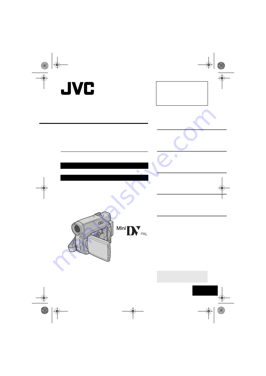
GR-D350EW

LYT1574-001A

EN

Dear Customer,

Thank you for purchasing this digital 
video camera. Before use, please 
read the safety information and 
precautions contained in the pages 
2 – 5 and 11 to ensure safe use of 
this product.

Please visit our Homepage on the World Wide Web for 
Digital Video Camera:

For Accessories

:

http://www.jvc.co.jp/english/cyber/

http://www.jvc.co.jp/english/accessory/

INSTRUCTIONS

DIGITAL VIDEO CAMERA

GETTING STARTED

8

VIDEO RECORDING & 
PLAYBACK

18

ADVANCED FEATURES

23

REFERENCES

36

TERMS

To deactivate the demonstration, 
set “DEMO MODE” to “OFF”. 
(

pg. 23, 25) 

43

GR-D350EW.book  Page 1  Friday, January 20, 2006  4:14 PM

Summary of Contents for GR-D350EW

Page 1: ...of this product Please visit our Homepage on the World Wide Web for Digital Video Camera For Accessories http www jvc co jp english cyber http www jvc co jp english accessory INSTRUCTIONS DIGITAL VIDEO CAMERA GETTING STARTED 8 VIDEO RECORDING PLAYBACK 18 ADVANCED FEATURES 23 REFERENCES 36 TERMS To deactivate the demonstration set DEMO MODE to OFF 墌 pg 23 25 43 GR D350EW book Page 1 Friday January ...

Page 2: ...ccessories are used in this camcorder This product includes patented and other proprietary technology and will operate only with JVC Data Battery Use the JVC BNVF707U VF714U VF733U battery packs Using generic non JVC batteries can cause damage to the internal charging circuitry Make sure you only use cassettes with the Mini DV mark Remember that this camcorder is intended for private consumer use ...

Page 3: ...ed If in doubt consult a competent electrician WARNING TO PREVENT FIRE OR SHOCK HAZARD DO NOT EXPOSE THIS UNIT TO RAIN OR MOISTURE CAUTIONS To prevent shock do not open the cabinet No user serviceable parts inside Refer servicing to qualified personnel When you are not using the AC Adapter for a long period of time it is recommended that you disconnect the power cord from AC outlet Blue to N Neutr...

Page 4: ...cularly susceptible to this type of injury Do not use a tripod on unsteady or unlevel surfaces It could tip over causing serious damage to the camcorder CAUTION Connecting cables Audio Video S Video etc to the camcorder and leaving it on top of the TV is not recommended as tripping on the cables will cause the camcorder to fall resulting in damage European Union This symbol indicates that the elec...

Page 5: ...hen it is unattended unless it is specifically stated that it is designed for unattended operation or has a standby mode Switch off using the switch on the equipment and make sure that your family knows how to do this Special arrangements may need to be made for infirm or handicapped people DON T use equipment such as personal stereos or radios so that you are distracted from the requirements of r...

Page 6: ...rd mode setting of the camcorder by pressing the AUTO button 墌 pg 14 Backlight Compensation Simply pressing the BACKLIGHT button brightens the image darkened by backlight 墌 pg 29 You can also select a spot metering area so that more precise exposure compensation is available 墌 pg 29 Spot Exposure Control Data Battery You can check the battery status by simply pressing the DATA button 墌 pg 13 Major...

Page 7: ...ck 21 Shuttle Search 21 Blank Search 21 Playback Snapshot 21 Connections To A TV Or VCR 22 ADVANCED FEATURES 23 MENUS FOR DETAILED ADJUSTMENT 23 Changing The Menu Settings 23 Recording Menus 24 Playback Menus 26 FEATURES FOR RECORDING 27 Wide Mode 27 Night Scope 27 Snapshot Record Still Image On Tape 27 Manual Focus 28 Exposure Control 28 Iris Lock 29 Backlight Compensation 29 Spot Exposure Contro...

Page 8: ...8 EN MasterPage Left GETTING STARTED Index GR D350EW book Page 8 Friday January 20 2006 4 14 PM ...

Page 9: ...ecording Start Stop Button 墌 pg 18 N Power Switch REC OFF PLAY 墌 pg 14 O Lock Button 墌 pg 14 P Cassette Open Eject Switch OPEN EJECT 墌 pg 17 Connectors The connectors are located beneath the covers Q Audio Video Output Connector AV 墌 pg 22 33 R S Video Output Connector S 墌 pg 22 33 S DC Input Connector DC 墌 pg 12 T Digital Video Connector DV IN OUT i LINK 墌 pg 34 35 i LINK refers to the IEEE1394 1...

Page 10: ... Appears when taking snapshot 墌 pg 27 Q Spot Exposure Control Indicator 墌 pg 29 Backlight Compensation Indicator 墌 pg 29 Iris Lock Indicator 墌 pg 29 Exposure Adjustment Indicator 墌 pg 28 R Wipe Fader Mode Indicator 墌 pg 31 S Wind Cut Indicator 墌 pg 25 T Time Code 墌 pg 25 U Manual Focus Adjustment Indicator 墌 pg 28 Brightness Control Indicator LCD monitor Viewfinder 墌 pg 16 V Date Time 墌 pg 15 Duri...

Page 11: ...nd camcorder are stored in a dusty area Cassette tapes should be removed from the camcorder and stored in cassette cases Store the camcorder in a bag or other container Use SP Standard mode for important video recordings LP Long Play mode lets you record 50 more video than SP Standard mode but you may experience mosaic like noise during playback depending on the tape characteristics and the usage ...

Page 12: ...f power Do not use provided power supply units with other equipment Charging The Battery Pack 1 Set the Power Switch to OFF 2 With the arrow on the battery pack pointing downward push the battery pack slightly against the battery pack mount a 3 Slide down the battery pack until it locks in place b 4 Connect the AC Adapter to the camcorder 5 Plug the AC Adapter into an AC outlet The POWER CHARGE la...

Page 13: ...pter In this case the battery charge starts if the battery is attached to the camcorder Using The Battery Pack Perform steps 2 3 in Charging The Battery Pack Maximum continuous recording time Provided NOTES Recording time is reduced significantly under the following conditions Zoom or Record Standby mode is engaged repeatedly The LCD monitor is used repeatedly The playback mode is engaged repeated...

Page 14: ...ow temperature condition or charged too many times To turn on the camcorder set the Power Switch to any operation mode except OFF while pressing down the Lock Button located on the switch Choose the appropriate operation mode according to your preference using the Power Switch Auto Manual Mode Press AUTO button repeatedly to switch to auto manual recording mode When manual mode is selected the ind...

Page 15: ... during playback 墌 pg 23 25 1 Perform steps 1 4 in Language Settings on the left column 2 Press or to select CLOCK ADJ and press SET or The date display format is highlighted 3 Press or to select the desired date display format and then press SET or Select from MONTH DATE YEAR DATE MONTH YEAR or YEAR MONTH DATE 4 Press or to select the time display format then press SET or Select from 24h or 12h 5...

Page 16: ...he viewfinder fully and set PRIORITY to FINDER 墌 pg 23 25 3 Press MENU The Menu Screen appears If you are in Playback mode please proceed to step 5 4 Press or to select DISPLAY and press SET or The DISPLAY Menu appears 5 Press or to select BRIGHT and press SET or The Menu Screen closes and the brightness control MENU appears 6 Press or until the appropriate brightness is reached and press SET or 7...

Page 17: ...e the battery pack with a fully charged one or use AC power before continuing 3 Close the cassette holder cover firmly until it locks into place To protect valuable recordings Slide the erase protection tab on the back of the tape in the direction of SAVE This prevents the tape from being recorded over To record on this tape slide the tab back to REC before loading it NOTES If you wait a few secon...

Page 18: ...Tape 墌 pg 20 To turn the melody sounds off 墌 pg 23 25 Tape Remaining Time Approximate tape remaining time appears on the display min means the camcorder is calculating the remaining time When the remaining time reaches 2 minutes the indication starts blinking The time required to calculate and display the remaining tape length and the accuracy of the calculation may vary according to the type of t...

Page 19: ... in the desired position and tilt the LCD monitor in the most convenient direction It can rotate 270 90 downward 180 upward Time Code During recording a time code is recorded on the tape This code is to confirm the location of the recorded scene on the tape during playback Frames are not displayed during recording If recording starts from a blank portion the time code begins counting from 00 00 00...

Page 20: ...mode 2 Tape is rewound for about several seconds and played back automatically then pauses in the Recording Standby mode for the next shot Distortion may occur at start of playback This is normal Recording From The Middle Of A Tape 1 Play back a tape or use Blank Search 墌 pg 21 to find the spot at which you want to start recording then engage the Still Playback mode 墌 pg 21 2 Set the Power Switch ...

Page 21: ... button normal playback resumes A slight mosaic effect appears on the display during Shuttle Search This is not a malfunction ATTENTION During Shuttle Search parts of the picture may not be clearly visible particularly on the left side of the screen Blank Search Helps you find where you should start recording in the middle of a tape to avoid time code interruption 墌 pg 19 1 Load a cassette 墌 pg 17...

Page 22: ...TV input referring to your VCR s instruction manual 4 Turn on the camcorder the VCR and the TV 5 Set the VCR to its AUX input mode and set the TV to its VIDEO mode 6 Start playback on the camcorder 墌 pg 21 To choose whether or not the following displays appear on the connected TV Date Time Set DATE TIME to ON or OFF 墌 pg 23 26 Time Code Set TIME CODE to ON or OFF 墌 pg 26 Indications other than dat...

Page 23: ... Menu 2 Press or Select the desired parameter and press SET or Selection is complete Repeat the procedure if you wish to set other function menus The indicator shows the setting that is currently saved inside the camcorder s memory 3 Press MENU The Menu Screen closes Video Playback Menus REC MODE 墌 pg 26 SOUND MODE 墌 pg 26 NARRATION 墌 pg 26 BRIGHT 墌 pg 26 DATE TIME 墌 pg 26 ON SCREEN 墌 pg 26 TIME C...

Page 24: ...les video recording of stereo sound on two separate channels Equivalent to the 48 kHz mode of previous models OFF Disables the function ON To compensate for unstable images caused by camera shake particularly at high magnification NOTES Accurate stabilisation may not be possible if hand shake is excessive or depending on the shooting condition The indicator blinks or goes out if the Stabiliser can...

Page 25: ...RLANDS The language setting can be changed 墌 pg 15 OFF The date time does not appear ON The date time is always displayed LCD Keeps the camcorder s display except the date time and time code from appearing on the connected TV screen LCD TV Makes the camcorder s display appear on screen when the camcorder is connected to a TV OFF Time code is not displayed ON Time code is displayed on the camcorder...

Page 26: ...tor does not appear on the screen STEREO Sound is output on both L and R channels in stereo SOUND L Sound from the L channel is output SOUND R Sound from the R channel is output Although it is not possible to perform audio dubbing with this camcorder you can hear sound from an audio dubbed tape during playback using this function OFF Original sound is output on both L and R channels in stereo ON D...

Page 27: ...d to provide up to 30 times sensitivity appears beside while the shutter speed is being automatically adjusted To deactivate Night Scope Press NIGHT again so that the Night Scope indicator disappears NOTES During Night Scope GAIN UP or DIS in SETTING Menu 墌 pg 24 cannot be activated Night Scope cannot be activated simultaneously with SNOW or SPORTS of PROGRAM AE or all modes of SHUTTER 墌 pg 32 Dur...

Page 28: ...lecting off the surface of a body of water When shooting a scene with a high contrast background The following low contrast warnings appear blinking and Manual exposure control is recommended in the following situations When shooting using reverse lighting or when the background is too bright When shooting on a reflective natural background such as at the beach or when skiing When the background i...

Page 29: ...eration backlight compensation feature brightens the dark subject portion by increasing the exposure 1 Set the Power Switch to REC 2 Set the recording mode to M 墌 pg 14 3 Press BACKLIGHT so that the Backlight Compensation indicator appears To cancel Backlight Compensation Press BACKLIGHT twice so that the indicator disappears NOTE Using Backlight Compensation may cause the light around the subject...

Page 30: ... to REC 2 Set the recording mode to M 墌 pg 14 3 Hold a sheet of plain white paper in front of the subject Adjust zoom or position yourself so that the white paper fills the screen 4 Select FUNCTION Menu 墌 pg 24 5 Select MWB in W BALANCE menu 墌 pg 24 then press and hold SET or until begins blinking When the setting is completed stops blinking 6 Press SET or to engage the setting 7 Press MENU The Me...

Page 31: ...ipes out from top to bottom leaving a black screen 1 Set the Power Switch to REC 2 Set the recording mode to M 墌 pg 14 3 Set EFFECT PROGRAM AE or SHUTTER in FUNCTION Menu 墌 pg 24 The EFFECT PROGRAM AE or SHUTTER menu disappears and the selected effect is activated The selected effect indicator appears To deactivate the selected effect Select OFF in step 3 The effect indicator disappears NOTES Prog...

Page 32: ...ed to your desired setting When Twilight is chosen the camcorder automatically adjusts the focus from approx 10 m to infinity From less than 10 m adjust the focus manually SHUTTER OFF Disables the function Factory preset SHUTTER 1 50 The shutter speed is fixed at 1 50th of a second Black bands that usually appear when shooting a TV screen become narrower SHUTTER 1 120 The shutter speed is fixed at...

Page 33: ...interference 1 Following the illustrations connect the camcorder and the VCR s input connectors 2 Start playback on the camcorder 墌 pg 21 3 At the point you want to start dubbing start recording on the VCR Refer to the VCR s instruction manual 4 To stop dubbing stop recording on the VCR then stop playback on the camcorder NOTES It is recommended to use the AC Adapter as the power supply instead of...

Page 34: ... appear in step 4 If this occurs turn off the power and make connections again When using a DV cable be sure to use the optional JVC VC VDV204U DV cable To use this camcorder as a recorder 1 Make sure all units are turned off 2 Connect this camcorder to a video unit equipped with a DV output connector using a DV cable as shown in the illustration 3 Set the camcorder s Power Switch to PLAY 4 Set RE...

Page 35: ...tor 4 or 6 pins on the PC The date time information cannot be captured into the PC Refer to the instruction manuals of the PC and Software The still images can also be transferred to a PC with a DV connector equipped capture board The system may not work properly depending on the PC or capture board you are using Connection To A Personal Computer PC with DV connector To DV IN OUT To DV connector C...

Page 36: ...ver is open HClose the cassette holder cover 墌 pg 17 HClean the video heads with an optional cleaning cassette 墌 pg 41 Advanced features Focus is set to the Manual mode HSet Focus to the Auto mode 墌 pg 28 The lens is dirty or covered with condensation HClean the lens and check the focus again 墌 pg 39 The 16 9 wide mode 16 9 indicator is selected HDisengage the 16 9 indicator 16 9 wide mode 墌 pg 27...

Page 37: ...s plugged unplugged with power turned on HTurn the camcorder s power off and on again then operate it In places subject to low temperature images become dark due to the characteristics of the LCD monitor This is not a malfunction HAdjust the brightness and angle of the LCD monitor 墌 pg 16 18 When the LCD monitor s fluorescent light reaches the end of its service life images on the LCD monitor beco...

Page 38: ...he date time is not set 墌 pg 15 The built in clock battery has run out and the previously set date time has been erased Consult your nearest JVC dealer for replacement Appears for 5 seconds after power is turned on if the lens cap is attached or when it is dark Appears when pictures recorded in the HDV format are detected The pictures in the HDV format cannot be played back with this camcorder The...

Page 39: ...o clean the lens Blow it with a blower brush then wipe gently with lens cleaning paper To clean the viewfinder lens Remove dust from the viewfinder using a blower brush NOTES Avoid using strong cleaning agents such as benzine or alcohol Cleaning should be done only after the battery pack has been removed or other power units have been disconnected Mould may form if the lens is left dirty When usin...

Page 40: ...y pack Cassettes To properly use and store your cassettes be sure to read the following cautions During use make sure the cassette bears the Mini DV mark be aware that recording onto prerecorded tapes automatically erases the previously recorded video and audio signals make sure the cassette is positioned properly when inserting do not load and unload the cassette repeatedly without allowing the t...

Page 41: ...ack During recording or playback the Head Clog Warning indicator appears Recording cannot be performed properly In such cases use an optional cleaning cassette Insert it and play back If the cassette is used more than once consecutively damage to the video heads may result After the camcorder plays back for about 20 seconds it stops automatically Also refer to the cleaning cassette s instructions ...

Page 42: ...ewfinder Electronic viewfinder with 0 33 colour LCD Speaker Monaural Format DV format SD mode Signal format PAL standard Recording Playback format Video Digital component recording Audio PCM digital recording 32 kHz 4 channel 12 BIT 48 kHz 2 channel 16 BIT Cassette Mini DV cassette Tape speed SP 18 8 mm s LP 12 5 mm s Maximum recording time using 80 min cassette SP 80 min LP 120 min S S Video outp...

Page 43: ...8 I Iris Lock 29 L LCD Monitor and Viewfinder 16 18 Loading A Cassette 17 M Manual Focus 28 Melody 25 Motor Drive Mode 27 N Night Scope 27 P Playback Sound 26 Power Linked Operation 15 Priority 25 Program AE 32 Q Quick Review 20 R Recording Capacity Tape 18 S Shutter Effect 32 Snapshot Mode 27 Sound Mode 24 26 Speaker Volume 21 Specifications 42 Spot Exposure Control 29 T Tape Speed REC MODE 24 26...

Page 44: ...MasterPage BackCover EN GR D350EW Printed in Malaysia 0106MAR PR VM 2006 Victor Company of Japan Limited EW GR D350EW book Page 44 Friday January 20 2006 4 14 PM ...

Reviews: