(No.52097)
DT-V1910CG/U
INSTRUCTIONS
DT
-V1910CG
MUL
TI-FORMA
T MONIT
OR
V
OLUME
SLO
T 1
A
B
DEGA
USS
MENU
MUTING
SCREENS
CHECK
ASPECT
AREA
MARKER
UNDER SCAN
PULSE CR
OSS
COLOR
OFF
SLO
T 2
C
D
SLO
T
3
PO
WER
E
F
INPUT SELECT
For Customer Use:
Enter below the Serial No. which is located on the rear of
the cabinet. Retain this information for future reference.
Model No.
:
DT
-V1910CG
Serial No.
:
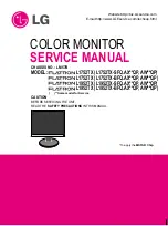
The illustration above shows the DT
-V1910CG with provided
wide mask attached.
LCT1316-001B
JVC PROFESSIONAL PRODUCTS COMPANY
DIVISION OF US JVC CORP.
1700 Valley Road Wayne, N.J. 07470
JVC CANADA INC.
21 Finchdene Square, Scarborough Ontario M1X 1A7
©
2003 VICT
OR COMP
ANY
OF JAP
AN, LIMITED
Printed in Japan
0103-MA-UN-VP
DT-V1910CG MULTI-FORMAT MONITOR
OPERATING INSTRUCTIONS