background image

SERVICE MANUAL

COPYRIGHT © 2003 VICTOR COMPANY OF JAPAN, LTD.

No.49776

2003/01

CH-X1500

CD CHANGER

49776

2003

01

CH-X1500

TABLE OF CONTENTS

1

Important Safety Precautions  . . . . . . . . . . . . . . . . . . . . . . . . . . . . . . . . . . . . . . . . . . . . . . . . . . . . . . . . . . . .1-2

2

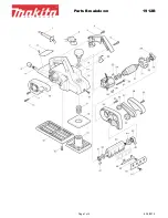
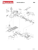
Disassembly method  . . . . . . . . . . . . . . . . . . . . . . . . . . . . . . . . . . . . . . . . . . . . . . . . . . . . . . . . . . . . . . . . . . .1-4

3

Adjustment method  . . . . . . . . . . . . . . . . . . . . . . . . . . . . . . . . . . . . . . . . . . . . . . . . . . . . . . . . . . . . . . . . . . .1-22

4

Description of major ICs  . . . . . . . . . . . . . . . . . . . . . . . . . . . . . . . . . . . . . . . . . . . . . . . . . . . . . . . . . . . . . . .1-30

Area Suffix


Northern America


Continental Europe


Other Areas

www. xiaoyu163. com

QQ 376315150

9

9

2

8

9

4

2

9

8

TEL 13942296513

9

9

2

8

9

4

2

9

8

0

5

1

5

1

3

6

7

3

Q

Q

TEL  13942296513  QQ  376315150  892498299 

TEL  13942296513  QQ  376315150  892498299 

http://www.xiaoyu163.com

http://www.xiaoyu163.com

Summary of Contents for CHX1500 - CD Changer

Page 1: ... Disassembly method 1 4 3 Adjustment method 1 22 4 Description of major ICs 1 30 Area Suffix J Northern America E Continental Europe U Other Areas www xiaoyu163 com QQ376315150 9 9 2 8 9 4 2 9 8 TEL 13942296513 9 9 2 8 9 4 2 9 8 0 5 1 5 1 3 6 7 3 Q Q TEL 13942296513 QQ 376315150 892498299 TEL 13942296513 QQ 376315150 892498299 http www xiaoyu163 com http www xiaoyu163 com ...

Page 2: ...r touch it in case of an adjustment or operation check This unit can only be connected to the JVC car receivers controllers equipped with MP3 CD changer control functions If connected to any other receiver controller this unit cannot work even CDs may not play back www xiaoyu163 com QQ376315150 9 9 2 8 9 4 2 9 8 TEL 13942296513 9 9 2 8 9 4 2 9 8 0 5 1 5 1 3 6 7 3 Q Q TEL 13942296513 QQ 376315150 8...

Page 3: ... Handling the traverse unit optical pickup 1 Do not subject the traverse unit optical pickup to strong shocks as it is a sensitive complex unit 2 Cut off the shorted part of the flexible cable using nippers etc after replacing the optical pickup For specific details refer to the replacement procedure in the text Remove the anti static pin when replacing the traverse unit Be careful not to take too...

Page 4: ...direction knob in the direction of the ar row using a coin etc to remove it The knob can be re moved only when it is set to this position 3 Remove the four screws B attaching the bottom cover on both sides of the main unit 4 Turn the unit upside down so the bottom surface is facing upward 5 Lift the rear edge of the bottom cover slightly and lift the side by grasping the DIN jack section on the si...

Page 5: ...required REFERENCE To reassemble refer to the diagram below Fig 5 Fig 6 Fig 6 1 Fig 7 Fig 8 Fig 9 Fig 9 1 Damper Damper Damper shaft Damper Push out with your finger before attaching Apply alcohol to the shaft then immediately attach the damper After attaching check that the shaft is correctly inserted Damper spring bracket Turn to the top position at a right angle then the push down to lift off D...

Page 6: ...ng the main board as sembly and remove 3 Disconnect the wire from connector CN602 on the main board assembly 4 Disconnect the wire from connector CN501 on the main board assembly 5 Disconnect the card wire from connector CN604 on the traverse mechanism board assembly Fig 11 E a b b G G F G CN501 CN602 Main board assembly CN604 www xiaoyu163 com QQ376315150 9 9 2 8 9 4 2 9 8 TEL 13942296513 9 9 2 8...

Page 7: ...ve it from the chassis Fig 12 Fig 13 2 4 3 Remove the positioning motor assembly See fig 14 1 Remove the two screws I attaching the positioning motor ATTENTION When removing the positioning motor assembly from chassis remove the spacer attaching the wires 2 Slightly lift the positioning motor assembly to remove it from the two burrs on the chassis Fig 14 H H Spring Sensor assembly Magazine lock ar...

Page 8: ... rear section facing down Rotate the third gear located on the bottom of the unit in the direc tion of the arrow clockwise until the front slider is moved to the outermost position 2 Remove the E washer attaching the front slider and re move from the chassis Fig 16 Third gear Rear slider Can be remove at the stud position At the wideness position Third gear Front slider E washer www xiaoyu163 com ...

Page 9: ... plate slightly 3 Move the top plate toward the rear of the unit to remove the upper rod from the top plate Fig 17 Fig 18 J J J Rod Top plate d J Top plate www xiaoyu163 com QQ376315150 9 9 2 8 9 4 2 9 8 TEL 13942296513 9 9 2 8 9 4 2 9 8 0 5 1 5 1 3 6 7 3 Q Q TEL 13942296513 QQ 376315150 892498299 TEL 13942296513 QQ 376315150 892498299 http www xiaoyu163 com http www xiaoyu163 com ...

Page 10: ... 2 Lift the lifter unit upward then remove the lower rod to re move the lifter unit from the chassis Fig 19 Fig 20 Remove this part first Proper orientation Elevator spring Lower rod Lifter unit www xiaoyu163 com QQ376315150 9 9 2 8 9 4 2 9 8 TEL 13942296513 9 9 2 8 9 4 2 9 8 0 5 1 5 1 3 6 7 3 Q Q TEL 13942296513 QQ 376315150 892498299 TEL 13942296513 QQ 376315150 892498299 http www xiaoyu163 com ...

Page 11: ... two screws L attaching the side bracket and remove the side bracket 2 Remove the three shafts on the traverse mechanism as sembly from the lifter unit Fig 22 K K Lifter bracket Lifter unit Traverse mechanism assembly Side bracket L L www xiaoyu163 com QQ376315150 9 9 2 8 9 4 2 9 8 TEL 13942296513 9 9 2 8 9 4 2 9 8 0 5 1 5 1 3 6 7 3 Q Q TEL 13942296513 QQ 376315150 892498299 TEL 13942296513 QQ 376...

Page 12: ...ve 6 Remove the middle gear REFERENCE Remove gears and motors only when required 7 Move the pickup assembly upward from the gear section and remove it from the traverse chassis assembly 8 Remove the two screws P attaching the rack arm and re move 9 Pull out the feed slide shaft assembly and remove 10 Remove the screw Q attaching the spring and remove CAUTION When reassembling connect the flexible ...

Page 13: ...R assembly See fig 29 1 Remove the two screws T retaining the chassis L and R assemblies 2 Slide the chassis L assembly toward the front and detach it then remove the chassis L upward Fig 29 R R Tray motor assembly Tray motor Tray motor holder S T T Chassis L assembly Chassis R assembly Front side www xiaoyu163 com QQ376315150 9 9 2 8 9 4 2 9 8 TEL 13942296513 9 9 2 8 9 4 2 9 8 0 5 1 5 1 3 6 7 3 Q...

Page 14: ...ced 4 To mount the rack arm first move the pickup to the middle position and fixing it with the screw P CAUTION When reassembling the mechanism board reattach the flexible wire to connector CN603 on the mechanism board and then unsolder the sorting round point Next reattach the mechanism board with screw M Fig 30 Fig 31 Fig 32 Fig 33 Fig 34 Pickup assembly Shaft holder Feed slide shaft assembly Mi...

Page 15: ...f the lifter unit is correctly inserted into the holes h of the side bracket unit After reassembled check that levers move together 4 Turn the lifter unit upside down As shown in Fig 37 slide the lever 30 mm away from the edge and then mount the lifter bracket L assembly Fig 35 Fig 36 Fig 37 e Lifter unit Traverse mechanism assembly Side bracket L L f e f h f g e Lifter bracket L assembly Shift in...

Page 16: ... the chassis R assembly by sliding it from the front side and then the two lib j jointed to the chassis L assembly 3 After reassembled fix with the screw T 4 Attach the elevator spring between the lifter unit and the chassis Fig 38 Fig 39 Fig 40 Lifter unit Lower rod Chassis R assembly i Attached Chassis R assembly Chassis L assembly T T Chassis L assembly Chassis R assembly j j www xiaoyu163 com ...

Page 17: ... bending sec tion of the top plate pinches section q of the lifter unit 3 Attach the top plate with six screws J Fig 41 Fig 42 Fig 43 Fig 44 Remove this part first Proper orientation Elevator spring k Upper rod J J J Rod Top plate l m n p o q o section Lifter unit www xiaoyu163 com QQ376315150 9 9 2 8 9 4 2 9 8 TEL 13942296513 9 9 2 8 9 4 2 9 8 0 5 1 5 1 3 6 7 3 Q Q TEL 13942296513 QQ 376315150 89...

Page 18: ...side facing down then mount the rear slider Check that the r s and t positions are correctly mounted as shown in Fig 46 5 Rotate the third gear in the direction of the arrow counter clockwise until the lifter unit is at the top position Fig 45 Fig 46 Psition so that the stud and right hole are lined up Front slider E washer Stud Lift arm Rotate until the holes are lined up Set the holes are expose...

Page 19: ...ain board See fig 48 1 Rotate the third gear clockwise until section u of the front slider and the third hole from the right are lined up Be sure to set properly If incorrectly set the switches on the assembly may be damaged 2 After they are correctly positioned mount the main board assembly Fig 48 Sensor board assembly Attach temporarity Shorter Shoter spring Longer spring Third gear Front slider...

Page 20: ...r and remove the pickup assembly CAUTION When replacing the pickup be sure to apply counter measures against static electricity grounding the oper ation table wrist band and soldering iron To remove it first sorting round point on the mechanism board then lift the mechanism board assembly with CN603 con nected Next sorting round point on the pickup main unit then unplug the pickup flexible board f...

Page 21: ...averse chassis O Shift approx 30mm Shift approx 30mm Lifter unit lever www xiaoyu163 com QQ376315150 9 9 2 8 9 4 2 9 8 TEL 13942296513 9 9 2 8 9 4 2 9 8 0 5 1 5 1 3 6 7 3 Q Q TEL 13942296513 QQ 376315150 892498299 TEL 13942296513 QQ 376315150 892498299 http www xiaoyu163 com http www xiaoyu163 com ...

Page 22: ...g the disc jam through the clearance at the top of the lifter Remove the lifter bracket L and return the tray to the magazine RESET Press EJECT for 3 sec Completed YES YES YES NO NO NO Remove the bottom cover Is the disc set in the playing position Are trays stored in the magazine Check visually Improperly positioned Peel off the sticker on the left side of the unit Insert a screwdriver and press ...

Page 23: ...en changing or ejecting discs YES 5 NO 6 5 Check that TRAY OUT SW S602 and TRAY IN SW S603 function correctly E4 Pick returning error Does the feed pickup unit return to the inner area of the disc when ejecting YES 7 NO 8 9 7 Check the rest switch 8 If the feed gear is rotated check the feed transfer mechanism 9 If the feed gear is not rotated check the motor driver and the pattern E8 Connection e...

Page 24: ...ct E1 03 00 18 MAG in switch Low to High Magazine removed when tray partly retracted E1 03 00 19 Lifter raise error Wait position time out Position motor inoperative E1 02 00 21 Wait position time out Position not stable in fine adjust mode E1 02 00 22 Wait position time out Other fault E1 02 00 23 Lifter lower error Wait position time out Position motor inoperative E1 02 00 26 Wait position time ...

Page 25: ...V Servo Mode Program Area CLV Servo Mode Lead In Area Digital 0 RF signal Focus Servo Loop ON TERMINAL Microprocessor commands Microprocessor commands Tracking Servo Loop ON Servo CLV Rough Servo Acceleration Acceleration Microprocessor commands Spindle motor 20 FMO TC9462 CN502 or CN503 FEED MOTOR IC581 RESET SW 83 82 81 5V Hi Z 0V 6V 4V 2V OFF ON SEL TC9462 LD 5V 0V 4V 0V 84 57 5 22 53 A200 86 8...

Page 26: ...ons to the receiver or the circuits in the vicinity of IC651 Check the linear position sensor VR601 Check the wiring of the CD 9 V power supply position motor Check the TRAY IN and TRAY OUT switches Exchange discs then check whether or not the feed motor moves Set from the STOP to PLAY mode then check that the triangle wave appears at IC581 pins H and I Does the laser emit Check the MAG SW TRAY IN...

Page 27: ...ins H and I 4V Is the disk rotated Does the RF signal appear at TP1 Is 4V present between IC581 pins 1 and 2 Check the spindle motor and its wiring Is 4V present at IC521 pin x Check the vicinity of IC581 Check IC501 and IC521 YES NO NO NO NO NO YES YES YES Check the circuits in the vicinity of IC501 J O or the pickup Is the RF waveform at TP1 distorted Proceed to the Tracking section When the dis...

Page 28: ...k IC521 and its peripheral circuits Is the audio signal including sampling output components output to IC521 pins and during Is the audio signal output at IC101 pins 1 and7during playback NO Check IC101 and its peripheral circuits Check the muting circuit Normal www xiaoyu163 com QQ376315150 9 9 2 8 9 4 2 9 8 TEL 13942296513 9 9 2 8 9 4 2 9 8 0 5 1 5 1 3 6 7 3 Q Q TEL 13942296513 QQ 376315150 8924...

Page 29: ...er diode is almost worn out and the laser pickup should be replaced If the semi fixed resistor is adjusted while the pickup is functioning normal ly the laser pickup may be damaged due to excessive cur rent 3 5 Replacement of laser pickup Is RF output 1 0 0 35Vp p Replace it NO YES O K Turn off the power switch and disconnect the power cord from the ac outlet Replace the pickup with a normal one R...

Page 30: ...positive analog output pin 11 AOUTL Lch negative analog output pin 12 AOUTL Lch positive analog output pin 13 VSS Ground pin 14 VDD Power supply pin 15 DZFR Rch data zero input detect pin 16 DZFL Lch data zero input detect pin De emphasis Control 8X Interpolator uP Interface Audio Data Interface CSN CCLK CDTI LRCK BICK SDTI PDN 8X Interpolator Modulator SCF SCF Clock Divider VDD VSS DZFL DZFR MCLK...

Page 31: ...ction 1 VOUT Reset output 2 SUB Sub slate connect to GND 3 N C Non connect 4 GND GND 5 VDD Power supply voltage www xiaoyu163 com QQ376315150 9 9 2 8 9 4 2 9 8 TEL 13942296513 9 9 2 8 9 4 2 9 8 0 5 1 5 1 3 6 7 3 Q Q TEL 13942296513 QQ 376315150 892498299 TEL 13942296513 QQ 376315150 892498299 http www xiaoyu163 com http www xiaoyu163 com ...

Page 32: ...switch terminal 10 IN4 CH4 input 11 IN3 CH3 input 12 IN1 CH1 input 13 IN2 CH2 input 14 GND1 Power GND BTL driver unit 15 OUT2 BTL driver CH2 output 16 OUT2 BTL driver CH2 output 17 OUT1 BTL driver CH1 output 18 OUT1 BTL driver CH1 output 19 OUT3 BTL driver CH3 output 20 OUT3 BTL driver CH3 output 21 OUT4 BTL driver CH4 output 22 OUT4 BTL driver CH4 output 23 LDCONT2 Loading driver CH6 voltage sett...

Page 33: ... CONTROL LOGIC HIGH VOLTAGE GEN Vcc LEVEL DETECT ACK START STOP Pin name I O Description Vcc Power supply GND Ground 0v A0A1A2 IN Slave address set SCL IN Serial clock input SDA IN OUT Slave and word addressserial data input serial data output 1 WP IN Write protect input www xiaoyu163 com QQ376315150 9 9 2 8 9 4 2 9 8 TEL 13942296513 9 9 2 8 9 4 2 9 8 0 5 1 5 1 3 6 7 3 Q Q TEL 13942296513 QQ 37631...

Page 34: ...m 14 13 12 11 10 9 8 1 2 3 4 5 6 7 Vcc 4C 4A 4Y 3C 3A 3Y 1C 1A 1Y 2C 2A 2Y GND Input Output C A Y L X Z H L L H H H 1Y 2Y 3Y 4Y 1A 1C 2A 2C 3A 3C 4A 4C www xiaoyu163 com QQ376315150 9 9 2 8 9 4 2 9 8 TEL 13942296513 9 9 2 8 9 4 2 9 8 0 5 1 5 1 3 6 7 3 Q Q TEL 13942296513 QQ 376315150 892498299 TEL 13942296513 QQ 376315150 892498299 http www xiaoyu163 com http www xiaoyu163 com ...

Page 35: ...AOUTPUT A INPUT A INPUT V B INPUT B INPUT B OUTPUT V GND 1 VIN 2 VOUT 3 5 STB 4 NC Short protect 3 VOUT 1 GND Vref VIN 2 STB 5 GND 1 1 2 3 5 4 PIN FUNCTION 1 GND 2 VIN 3 VOUT 4 NC 5 STB www xiaoyu163 com QQ376315150 9 9 2 8 9 4 2 9 8 TEL 13942296513 9 9 2 8 9 4 2 9 8 0 5 1 5 1 3 6 7 3 Q Q TEL 13942296513 QQ 376315150 892498299 TEL 13942296513 QQ 376315150 892498299 http www xiaoyu163 com http www ...

Page 36: ...75k 1 3V 2k 1k 180k 3k 12k 12k 20k 40k 30k 10pF 50 A BOTTOM PEAK K 1 x0 5 x2 x0 5 x2 PIN SEL APC SW TEB TE BAL RFGC AGC Gian TEB TE BAL VCTRLPIN VCC APC ON 50 12dB Normal mode 0dB HiZ APC ON 0 6dB Normal mode 0dB GND APC OFF LDO H 50 0dB CD RW mode 12dB www xiaoyu163 com QQ376315150 9 9 2 8 9 4 2 9 8 TEL 13942296513 9 9 2 8 9 4 2 9 8 0 5 1 5 1 3 6 7 3 Q Q TEL 13942296513 QQ 376315150 892498299 TEL...

Page 37: ...rence voltage VRO output pin VRO 1 2VCC When VCC 3 3V 15 FEO O Focus error signal generation amp output pin 16 FEN I Focus error signal generation amp negative phase input pin 17 RFRP O Signal amp output pin for track count Combining RFRP signal and TEO signal with TC94A14F FA configures tracking search system 18 19 20 REIS RFGO RFGC I O I RF signal amplitude adjustment amp output pin RF amplitude...

Page 38: ...SB first or LSB first selectable by command 4 DOUT O Digital data output pin Outputs up to double speed playback 5 IPF O Correction flag output pin When set to H AOUT output cannot be corrected by C2 correction processing 6 VDD3 Digital 3 3V power supply voltage pin 7 VSS3 Digital GND pin 8 SBOK O Subcode Q data CRCC result output pin H level when result is OK 9 CLCK O Subcode P W data read I O pi...

Page 39: ...alizer output pin 42 VSS3 Digital GND pin 43 VDD3 Digital 3 3V power supply voltage pin 44 TESIN I Test input pin Normally fixed to L 45 XVSS3 System clock oscillator GND pin 46 XI I System clock oscillator input pin 47 XO O System clock oscillator output pin 48 XVDD3 System clock oscillator 3 3V power supply voltage pin 49 DVSS3R DA converter GND pin 50 RO O R channel data forward output pin 51 D...

Page 40: ...inter register X Pointer register ERAM 2k word CROM 4k word 7 Y RAM 4k word X RAM 4k word Flag Timer register X0 X1 X2 Y0 Y1 Y2 MX AX AY MY MZ ALU A2 A1 A0 A3 round limit round limit Audio I F Microcom I F MAC Program control Instruction decoder PROM 4k 3 12k word PRAM 256word 1Mbit SRAM SRAM I F Interrupt control DRAM I F General inputbport SubCode I F VCO Timing generator www xiaoyu163 com QQ376...

Page 41: ...Po0 Po3 O General purpose output 0 3 35 VDDT Power supply for digital 3 3V 36 38 Po4 Po6 O General purpose output 4 6 39 REQ O REC terminal 40 VSS GND for digital 41 IRO I O External interrupt input 42 VDDM Internal 1Mbit SRAM power supply 2 5V 43 44 Fi0 Fi1 I Flug input 0 1 45 VSSM GND for internal 1Mbit SRAM 46 47 Pi0 Pi1 I General ourpose input 01 48 VSS GND for digital 49 50 Pi2 Pi3 I General ...

Page 42: ... AVDD Connect to AD CONT power supply for A D converter 25 IOP I Pickup IOP measurement input 26 29 KEY0 3 I Key input 0 3 8bit A D input 30 TEMP IN I Temp detection input 31 L SENSOR I Linear senser input 8bit A D input 32 NC I Non connect connect to GND 33 GND GND for A D converter 34 ADCONT O Out put H at power ON stop mode L 35 V CONT O Position motor voltage control analog output 36 VREF Refe...

Page 43: ...ta 76 MP3 RESET O CD MP3 reset 77 MP3 STB O CD MP3 standby output H standby 78 CD CHECK I CD CHECK mode input only reset mode 79 LED O Lifter LED output 80 EPROM CLR I EPROM clear input 81 VDD Connect to 5V 82 MAG IN I Magazin switch L magazin in 83 TRAY IN I Tray return switch L complete return 84 TRAY OUT I Tray loading switch L complete loading 85 REST I Rest switch 86 DAC PDN O DAC power down ...

Page 44: ... Japan VICTOR COMPANY OF JAPAN LIMITED 2003 01 Printed in Japan www xiaoyu163 com QQ376315150 9 9 2 8 9 4 2 9 8 TEL 13942296513 9 9 2 8 9 4 2 9 8 0 5 1 5 1 3 6 7 3 Q Q TEL 13942296513 QQ 376315150 892498299 TEL 13942296513 QQ 376315150 892498299 http www xiaoyu163 com http www xiaoyu163 com ...

Page 45: ...l Europe Other Areas CD ROM No SML200301 Contents Block diagram Standard schematic diagrams Printed circuit boards 2 1 2 2 2 6 7 www xiaoyu163 com QQ376315150 9 9 2 8 9 4 2 9 8 TEL 13942296513 9 9 2 8 9 4 2 9 8 0 5 1 5 1 3 6 7 3 Q Q TEL 13942296513 QQ 376315150 892498299 TEL 13942296513 QQ 376315150 892498299 http www xiaoyu163 com http www xiaoyu163 com ...

Page 46: ...em Safety precaution Please use enough caution not to see the beam directly or touch it in case of an adjustment or operation check www xiaoyu163 com QQ376315150 9 9 2 8 9 4 2 9 8 TEL 13942296513 9 9 2 8 9 4 2 9 8 0 5 1 5 1 3 6 7 3 Q Q TEL 13942296513 QQ 376315150 892498299 TEL 13942296513 QQ 376315150 892498299 http www xiaoyu163 com http www xiaoyu163 com ...

Page 47: ...gram www xiaoyu163 com QQ376315150 9 9 2 8 9 4 2 9 8 TEL 13942296513 9 9 2 8 9 4 2 9 8 0 5 1 5 1 3 6 7 3 Q Q TEL 13942296513 QQ 376315150 892498299 TEL 13942296513 QQ 376315150 892498299 http www xiaoyu163 com http www xiaoyu163 com ...

Page 48: ... 22K BR24C01AFV 1000P QAX0617 001Z 3 9K 1000P 820 27P 8P 100k 100k 100k 100k 47 6 3 0 01 2 2K 10K 220 10 0 01 3 9K 47k 47K 47K 47K 10K 10K 10K 10K 47 6 3 47 6 3 470P 470P 39k 47K 100 6 3 47K 100K 1K 10K 2SC2412K 3 9K 3 9K 3 9K 22K 22K 330K 1 8u 100K 330 0 1 1 8u 100K 0 01 HD74HCT126T CD8V CDR POSCON BUSI O BUSSI CDRW BUSSO BUSSCK POSMO POSMO BUS0 TRAYMO BUS1 SHOCK 5V MP3REQ POSCON TRAYIN TRAYOUT R...

Page 49: ...02S 470 2SA1037AK R 22K 2SD1994 RS 220 0 1 47u 7K 7K 7K 7K 10 16 10 16 470 470 470P 470P 2K QSW0643 001Z AD0022 103X 0 1 1SS355 0 01 QNZ0095 001 2 2K BR24C01AFV NJM4565V 2200 16 0 01 10K 3 9K 2 2K 100 16 4 7K 100 10 0 01 UDZS6 2B 2SA1037AK R 27K 22K 180K ICP N70 QGA2501F1 03 0 01 10 3 3K 10 16 0 01 UDZS9 1B 0 01 47 16 0 01 QGF1009F2 10 QGF1013F1 10X 1 2K 470 0 01 2 7K 2SC2412 R 100K UDZS9 1B 47 16...

Page 50: ...6 3 0 1 470 0 01 4 3k 82k 0 47k 10 10 QGF1013F1 15X QGF1012F1 26X TA2157FN QAX0413 001Z 10P 10P 47 0 1 10k QGF1009F2 26 47 6 3 0 01 22 22 82k 0 01 0 1 0 1 56k 47 6 3 100 100 0 100 100 100P 47 6 3 220 220 220 47 6 3 0 01 4 7k 4 7k 4 7k 4 7k 10k 47 6 3 0 01 0 01 47 6 3 100P 47u 100P 100P 10 6 3 QGA2501F1 02 0 01 100 10 VE MD CDRW LD DVR BUS0 DMO FMO BUS3 BUS2 BUS1 BUCK TRO CCE DSPRST FOO TRAYMO TRAY...

Page 51: ...330 0 027 0 33 47 6 3 100k 0 1 0 1 0 1 0 01 47u 2SB1184 QR 10 10 2SB1132 QR 47 6 3 HD74HCT126T 330 1k 1k 82k 47 6 3 100 100 0 1 0 047 0 047 0 047 47 6 3 0 015 15k 47 6 3 NJU7241F33 NJU7241F25 DSK10C 470p 0 01 10 6 3 47 6 3 0 01 47u 47 6 3 47u 0 1 220 0 01 0 01 0 1 100P 47 6 3 0 1 100P 100 10 0 1 MP3STB CD8V 5V CDL SEL TEB RFGC TE RFDC RFRP MP3CK FE RF CKING CKING FOCUS FOCUS TRAY TRAY GND MP3RST M...

Page 52: ...155 R157 R158 R162 R163 R201 R253 R254 R255 R257 R258 R262 R263 R501 R502 R503 R505 R507 R508 R509 R510 R513 R518 R519 R525 R534 R535 R536 R537 R538 R541 R542 R544 L542 R548 R549 R550 R551 R601 R602 R603 R604 R609 R610 R611 R612 R613 R621 R622 R623 R624 R625 R626 R627 R628 R637 R639 R644 R651 R674 R903 R941 R942 R943 R951 R954 R981 S501 S502 TH501 X501 X621 R646 IC681 R645 R647 C511 C124 C9511 C95...

Page 53: ... R221 R222 R251 R252 R256 R259 R261 R504 R506 R511 R512 R514 R515 R516 R517 R520 R521 R522 R523 R524 R526 R527 R528 R529 R530 R531 R532 R533 R539 R540 L541 R545 R546 R605 R606 R607 R608 R614 R615 R616 R629 R630 R631 R635 R636 R638 R640 R641 R642 R643 R654 R675 R677 R681 R682 R683 R684 R685 R691 R692 R693 R694 R901 R902 R911 R912 R921 R923 R924 R925 R926 R971 R972 R973 R982 S501 S502 X501 X621 C691...

Page 54: ...Maebashi city 371 8543 Japan No 49776SCH Printed in Japan 200301 www xiaoyu163 com QQ376315150 9 9 2 8 9 4 2 9 8 TEL 13942296513 9 9 2 8 9 4 2 9 8 0 5 1 5 1 3 6 7 3 Q Q TEL 13942296513 QQ 376315150 892498299 TEL 13942296513 QQ 376315150 892498299 http www xiaoyu163 com http www xiaoyu163 com ...

Page 55: ...ock No MA Electrical parts list Block No 01 Packing materials and accessories parts list Block No M3 M5 CH X1500 3 2 3 4 3 7 3 10 Area suffix E Continental Europe J Northern America U Other Areas www xiaoyu163 com QQ376315150 9 9 2 8 9 4 2 9 8 TEL 13942296513 9 9 2 8 9 4 2 9 8 0 5 1 5 1 3 6 7 3 Q Q TEL 13942296513 QQ 376315150 892498299 TEL 13942296513 QQ 376315150 892498299 http www xiaoyu163 com...

Page 56: ... 23 22 21 15 19 1 14 5 2 3 4 10 24 17 27 28 12 26 18 17 9 17 16 17 16 12 25 17 30 31 32 29 32 32 32 30 31 30 31 30 31 www xiaoyu163 com QQ376315150 9 9 2 8 9 4 2 9 8 TEL 13942296513 9 9 2 8 9 4 2 9 8 0 5 1 5 1 3 6 7 3 Q Q TEL 13942296513 QQ 376315150 892498299 TEL 13942296513 QQ 376315150 892498299 http www xiaoyu163 com http www xiaoyu163 com ...

Page 57: ...REW 6 18 QYSDST2604M SCREW 2 19 QYSDST2005Z SCREW 2 PWB TOP 20 QYSDST2606Z SCREW 1 8P TOP 21 LV21396 001A F PANEL ASS Y U 1 LV21396 002A F PANEL ASS Y E 1 LV21396 004A F PANEL ASS Y J 1 FOR CH X1500 22 LV30786 003A HOLD BRACKET 1 23 QYSDSF2005Z SCREW 2 DOOR 3 HOLD BKT 24 LV33919 001A NAME PLATE J 1 LV33920 001A NAME PLATE E 1 LV33921 001A NAME PLATE U 1 25 VYSS2R2 028 SPACER 1 26 LV40762 001A CAUT...

Page 58: ...73 76 74 66 65 55 55 51 53 52 50 56 56 28 29 31 57 49 46 47 44 33 45 48 54 7 58 CD changer mechanism assembly and parts list Block No M M M A The edge part on the back side G B A F C G E E D D E Sencer board Main board Mechanism board b a To general assembly a F A C B Both side b 2 1 0 1mm 5 5 mm 0 1 0 E www xiaoyu163 com QQ376315150 9 9 2 8 9 4 2 9 8 TEL 13942296513 9 9 2 8 9 4 2 9 8 0 5 1 5 1 3 ...

Page 59: ...R SPRING 1 24 LV40478 002A EJECT DAMPER 1 25 QYSDSR2006Z SCREW 1 26 LV10027 002A TOP COVER 1 27 LV30101 004A MAGAZINE SPRING 3 28 QYSDST2004Z SCREW 9 29 LV30448 001A FRONT SLIDER AS 1 30 LV30449 001A REAR SLIDER ASS 1 31 LV42132 001A E RING 1 32 LV40135 004A ROD U 1 33 LV40136 003A ROD L 1 34 LV30104 002A SENSOR BRACKET 1 35 LV30105 001A SENSOR HOLDER 1 36 QVY0002 B14 S V RESISTOR 1 37 WJM0017 002...

Page 60: ...1A SCREW SHAFT 1 67 LV30122 002A SHAFT HOLDER 1 68 VKZ4248 204 MINI TAP SCREW 1 69 LV30123 002A RACK ARM 1 70 QYSPSPT1722M MINI SCREW 2 71 LV32438 001A P S SPRING 1 72 QYSPSGT1425M TAP SCREW 1 73 LV30450 004A PICK FPC 1 74 QYSDST2006Z SCREW 3 75 QYSDST2005Z SCREW 4 76 QUQ710 2614BJ FFC WIRE 1 77 QUQ110 1013BJ FFC WIRE 1 78 QYSDSP2606Z SCREW 1 41 1 LV30110 001A HOOK 1 41 2 VKR3203 001 CLAMPER 1 41 ...

Page 61: ...NCB31CK 473X C CAPACITOR C 637 NCB31CK 473X C CAPACITOR C 638 NDC31HJ 101X C CAPACITOR C 639 QERF0JM 476Z E CAPACITOR 47MF 20 6 3V C 640 NDC31HJ 100X C CAPACITOR C 641 NDC31HJ 100X C CAPACITOR C 642 NCB31HK 103X C CAPACITOR C 643 QERF0JM 476Z E CAPACITOR 47MF 20 6 3V C 644 NDC31HJ 101X C CAPACITOR C 645 NCB31CK 104X C CAPACITOR C 647 NCB31HK 103X C CAPACITOR C 648 NCB31CK 104X C CAPACITOR C 649 QE...

Page 62: ...NRSA63J 471X MG RESISTOR R 221 NRSA63J 391X MG RESISTOR R 222 NRSA63J 391X MG RESISTOR R 251 NRSA63J 472X MG RESISTOR R 252 NRSA63J 472X MG RESISTOR R 253 NRSA63J 222X MG RESISTOR R 254 NRSA63J 222X MG RESISTOR R 255 NRSA63J 392X MG RESISTOR R 256 NRSA63J 392X MG RESISTOR R 257 NRSA63J 103X MG RESISTOR R 258 NRSA63J 103X MG RESISTOR R 261 NRSA63J 223X MG RESISTOR R 262 NRSA63J 471X MG RESISTOR R 2...

Page 63: ...221X MG RESISTOR R 674 NRSA63J 331X MG RESISTOR R 675 NRSA63J 331X MG RESISTOR R 677 NRSA63J 105X MG RESISTOR R 681 NRSA63J 432X MG RESISTOR R 682 NRSA63J 823X MG RESISTOR R 683 NRSA63J 0R0X MG RESISTOR R 684 NRSA63J 473X MG RESISTOR R 691 NRSA63J 102X MG RESISTOR R 692 NRSA63J 102X MG RESISTOR R 693 NRSA63J 221X MG RESISTOR R 694 NRSA63J 331X MG RESISTOR R 901 NRSA63J 103X MG RESISTOR R 902 NRSA6...

Page 64: ...10 A11 A14 P8 P2 P1 P4 P2 P3 A15 2 2 1 2 P6 A9 A1 A8 KIT A12 A13 P5 P7 www xiaoyu163 com QQ376315150 9 9 2 8 9 4 2 9 8 TEL 13942296513 9 9 2 8 9 4 2 9 8 0 5 1 5 1 3 6 7 3 Q Q TEL 13942296513 QQ 376315150 892498299 TEL 13942296513 QQ 376315150 892498299 http www xiaoyu163 com http www xiaoyu163 com ...

Page 65: ... 1 ENG SPA FRE A 2 BT 51018 3 WARRANTY CARD J 1 A 3 BT 51028 2 J REGIST CARD J 1 A 4 BT 20071B JVC CENTER LIST J 1 A 5 BT 52006 2 WARRANTY CARD J 1 A 6 LVT0770 002C INST SHEET E 1 LVT0918 001B INST SHEET U 1 LVT0770 003C INST SHEET J 1 MP3 A 7 LVT0327 001B TROUBLE SHOOTIN J 1 A 8 BT 54013 5 WARRANTY CARD E 1 A 9 LV33160 001A MAGAZINE ASS Y E 1 LV30682 205A CL MAGAZINE ASS Y J U 1 A 10 LV21416 001A...

Reviews: