


BR-HD5
0
H
D
V
IDE
O CA
S
S
E
T
T
E
RE
CORDE
R
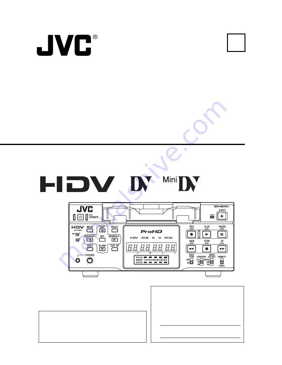
BR-HD50
E
HD VIDEO CASSETTE RECORDER
INSTRUCTION MANUAL
LLT0088-001A-H
Thank you for purchasing this JVC product.
Before operating this unit, please read the
instructions carefully to unsure the best possi-
ble performance.
For Customer Use:
Enter below the Serial No. which is
located on the rear of cabinet. Retain
this information for future reference.
Model No. BR-HD50U/BR-HD50E
Serial No.
is a registered trademark owned by Victor Company of Japan, Limited.
is a registered trademark in Japan, the U.S.A., the U.K. and many other countries.
2005 Victor Company of Japan, Limited
Printed in Thailand
LLT0088-001A-H
Summary of Contents for BR-HD50U - Compact HDV/DV Format Video Recorder
Page 91: ......


