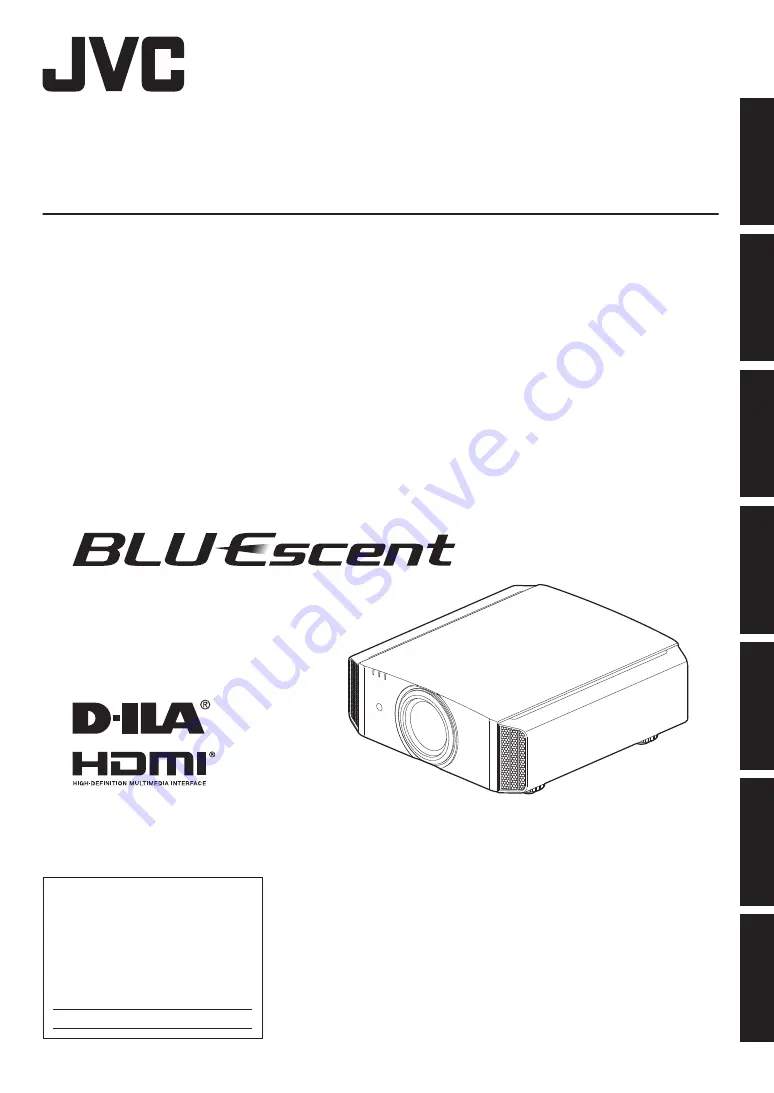
background image

.

D-ILA

PROJECTOR

DLA-VS2500ZG

DLA-VS2500G

DLA-VS2300ZG

DLA-VS2300G

.

.

For Customer use :

Enter below the serial No. which is

located on the back of the cabinet.

Retain this information for future

reference.

DLA-VS2500ZG

DLA-VS2500G

DLA-VS2300ZG

DLA-VS2300G

Model No.

Serial No.

INSTRUCTIONS

B5A-0626-10

Getting Started

Set up

Operate

Adjust/Set

Maintenance

Troubleshooting

Others

Summary of Contents for BLU-ESCENT DLA-VS2300G

Page 1: ...Enter below the serial No which is located on the back of the cabinet Retain this information for future reference DLA VS2500ZG DLA VS2500G DLA VS2300ZG DLA VS2300G Model No Serial No INSTRUCTIONS B5A 0626 10 Getting Started Set up Operate Adjust Set Maintenance Troubleshooting Others ...

Page 2: ...E LENS COVER BEFORE TURNING ON THE PROJECTOR CAUTION To reduce the risk of electric shock do not remove cover Refer servicing to qualified service personnel This projector is equipped with a 3 blade grounding type plug to satisfy FCC rule If you are unable to insert the plug into the outlet contact your electrician FCC INFORMATION U S A only CAUTION Changes or modification not approved by JVC coul...

Page 3: ...spilled or objects have fallen on the product If the product has been exposed to rain or water If the product does not operate normally by following the operating instructions Adjust only those controls that are covered by the Operation Manual as an improper adjustment of controls may result in damage and will often require extensive work by a qualified technician to restore the product to normal ...

Page 4: ...e picture element There is no problem with the playback of moving images e g normal video footage Video images can burn into the electronic com ponent parts Please do not display screens with still images of high brightness or high contrast such as found in video games and computer programs Over a long period of time it might stick to the picture element There is no problem with the playback of mo...

Page 5: ...SS 2 LASER PRODUCT DO NOT STARE INTO BEAM This CLASS 2 LASER PRODUCT label and Caution label are located on the TOP Side surface of the projector Light source specifications 30 W Laser diodes 2 Wavelength 450 460 nm Maximum output is 64 12 W Beam divergence angle from lens of this unit Wide α 62 7 Tele α 33 5 Location information of the labels α Laser emission port 5 Getting Started ...

Page 6: ...truction given below Dear Customer This apparatus is in conformance with the valid European directives and standards regarding electromagnetic compatibility and electrical safety European representative of JVC KENWOOD Corporation is JVC Technical Services Europe GmbH Konrad Adenauer Allee 1 11 61118 Bad Vilbel Germany THIS APPARATUS MUST BE EARTHED IMPORTANT Europe only The wires in the mains lead...

Page 7: ...an dass diese Batterie Blei enthalt FRANÇAIS Information sur l élimination des anciens équipements électriques et électroniques et piles électriques applicable dans les pays de qui ont adopté des systèmes de collecte sélective Les produits et piles électriques sur lesquels le pictogramme poubelle barrée est apposé ne peuvent pas être éliminés comme ordures ménagères Les anciens équipements électri...

Page 8: ...os perjudiciales en la salud y el medio ambiente Nota El símbolo Pb debajo del símbolo en baterías indica que dicha batería contiene plomo ITALIANO Informazioni sull eliminazione dei prodotti elettrici ed elettronici e delle batterie per i Paesi che adottano la raccolta differenziata dei rifiuti I prodotti e le batterie recanti questa icona bidone carrellato della spazzatura con il simbolo della c...

Page 9: ...essory 21 Operate Viewing Videos 22 Adjust Set Adjustments and Settings in the Menu 24 List of Menu Items 24 Picture Adjust 26 Input Signal 30 Installation 32 Display Setup 37 Function 38 Information 39 Maintenance Maintaining the Cabinet and Remote Control Sold Separately 40 Cleaning and Replacing the Filter 41 Troubleshooting Troubleshooting 42 When the following messages appear 44 Others Extern...

Page 10: ...s Optional Accessories Check the Accessories Power cord for USA about 2 m 1 piece Power cord for EU about 2 m 1 piece Optional Accessories 0 Remote control Model no RM MH13G 0 AAA size battery 10 Getting Started ...

Page 11: ...o Indicator Display on the Main Unit p 52 E Exhaust vent Warm air is discharged to cool down the internal temperature Do not block the vents Main Unit Bottom F Inlets at 3 points on the rear bottom The inlets take in air to cool down the internal temperature Do not block or prevent the outflow of hot air Doing so may cause the unit to malfunction There are two inlets on the right and left sides at...

Page 12: ...Remote Sensor rear Please aim the remote control sold separately at this area when using it There is also a remote sensor at the front K Power input terminal Connect the supplied power cord to this terminal Operation panel MENU Displays the menu BACK Returns to the previous menu JKH I keys Selects an item OK Confirms a selection INPUT Switches the input A STANDBY ON Turns on off the power 12 Getti...

Page 13: ...ew hole is 3 mm C LAN terminal RJ 45 The projector can be controlled by connecting it to a PC through the computer network for control commands to be sent to the projector D RS 232C terminal D sub 9 pin male The projector can be controlled by connecting a PC to this terminal E REMOTE terminal stereo mini jack This terminal is used to connect the remote control directly to the projector with the ca...

Page 14: ...level p 28 I COLOR TEMP For setting the color temperature p 28 J C M D For setting frame interpolation p 29 K LIGHT Illuminates the buttons on the remote control L OK Confirms a selected item M BACK Returns to the previous menu N PICTURE MODE Switches the Picture mode to NATURAL DYNAMIC USER1 to USER6 p 26 O PIC ADJ Switches the items for adjusting the image quality such as contrast brightness etc...

Page 15: ...remotecontroltowardthesensoronthis unit front or rear ensure that the distance to the sensor is within 7 m If the remote control fails to work properly move closer to this unit 30 30 20 20 Remote Control This unit Control through reflection off a screen etc Ensure that the total of distance A between this unit and the screen and distance B between the remote control and the screen is within 7 m As...

Page 16: ...annot be removed Maintain clearance from the wall etc As the unit discharges a large amount of heat install it with adequate clearance from the surroundings as shown below Front 150 mm and above 200 mm and above 300 mm and above 300 mm and above 150 mm and above Leave the front area of the unit unblocked If there is any obstructing object in front of the exhaust vent hot air will flow back to the ...

Page 17: ...t on your own may cause the unit to fall resulting in injury 0 Take the necessary actions to prevent the main unit from falling off such as during an earthquake 0 Regardless of the warranty period JVC is not liable for any product damage caused by mounting the unit with non JVC ceiling fittings or to an environment that is not suited for ceiling mount 0 When using the unit with it suspended from a...

Page 18: ...Lens shift Range Up to about 80 of the projected image Horizontal Position 0 Center Vertical Position Up to about 34 of the projected image Vertical Position 0 Center Horizontal Position Lens shift range 0 The maximum vertical shift varies with the amount of horizontal shift Similarly the maximum horizontal shift also changes with the amount of vertical shift 0 The values on the graph are intended...

Page 19: ...of their connector cover Connecting to the HDMI Input Terminal Digital Input Connecting via HDMI cable HDMI Output Terminal Laptop etc HDMI Cable Sold Separately This Unit To HDMI 1 or HDMI 2 input terminal Or both HDMI1 and HDMI2 0 If noise occurs move the laptop away from this unit 0 For a transmission bandwidth in compliance with the HDMI standard a cable which supports 340 MHz bandwidth is rec...

Page 20: ...For more information on control please refer to External Control p 45 Connecting to the RS 232C Terminal RS 232C Terminal Laptop etc RS 232C Connection Cable Sold Separately To RS 232C Terminal This Unit 0 For more information on control please refer to External Control p 45 Connecting to the REMOTE Terminal Wired Remote Controller Sold Separately Connection Cable Sold Separately To REMOTE Termina...

Page 21: ... Please connect it directly to the wall outlet 0 Pull out the power plug when the unit is not to be used for a prolonged period of time 0 Connect it using only the power cord supplied 0 Do not use a voltage other than the indicated power voltage 0 Do not damage break or modify the power cord Do not place a heavy object on the power cord or heat or pull it Doing so may damage the power cord 0 Do no...

Page 22: ...er light source startup 2 Choose the image to project Projector unit press the INPUT button pressing the button each time switches the mode HDMI 1 HDMI 2 Dual Remote control sold separately Button Terminal HDMI 1 HDMI1 HDMI 2 HDMI2 COMP Dual 0 Play back the selected device to project the image The Dual function is available only on 2 To hide the image temporarily Press the HIDE button on the proje...

Page 23: ...about 5 seconds the STANDBY ON indicator switches from a blinking red to a solid red light LIGHT WARNING STANDBY ON LIGHT WARNING STANDBY ON ND TANDBY In standby state STANDBY ON lights up red In the Cool down mode STANDBY ON blinking red CAUTION 0 After the light goes off the fan will run for about 5 seconds to cool down the laser light source Cool down mode Do not disconnect the power cable whil...

Page 24: ... Aperture p 26 9 User Name Edit p 26 IColor Management p 27 IColor Temp p 28 IGamma p 28 I4K e shift p 28 IClear Motion Drive p 29 IContrast p 29 IBrightness p 29 IColor p 29 ITint p 29 IReset p 29 Input Signal IInput Level p 30 IColor Space p 30 IHide p 30 IMask p 31 IPicture Position p 31 Installation ILens Control p 32 9 Focus p 32 9 Zoom p 32 9 Shift p 32 9 Image Pattern p 32 9 Lock p 32 9 Len...

Page 25: ...Display Setup IBack Color p 37 IMenu Position p 37 ISignal Display p 37 ILogo p 37 Function IOff Timer p 38 INetwork p 38 IRemote Code p 38 IHIDE Mode p 38 Information IInformation p 39 25 Adjust Set ...

Page 26: ... and settings Auto Intensity may not function LD Current If Auto Intensity is off light intensity is manually set using the gauge If Auto Intensity is on the LD Current gauge is grayed out The gauge moves to indicate the Auto Intensity control Aperture P For adjusting the amount of opening of the optical iris 0 Stopping down the iris reduces the brightness while opening it up increases the contras...

Page 27: ...al axis of the selected color Hue 30 to 30 Adjusts the hue color tone Saturation 30 to 30 Adjusts the color saturation vividness 30 dull to 30 vivid Brightness 30 to 30 Adjusts the brightness 30 dark to 30 bright 0 Selecting Reset resets all the adjustment data 0 Pressing the HIDE button enables you to check the image before adjustment MENU BACK 0 0 0 0 On A B Magenta Blue Cyan Green Yellow Red Cl...

Page 28: ... the video image 0 Setting range 255 reduces the red green blue tone to 0 enhances the red green blue tone Offset Red Offset Green Offset Blue Adjusts each color in the dark areas of the video image 0 Setting range 50 reduces the red green blue tone to 50 enhances the red green blue tone Gamma You can adjust the gamma curve of the projected image with respect to the video signal input Setting Desc...

Page 29: ... is the abbreviation for Clear Motion Drive Contrast For adjusting the difference in brightness to produce an image with contrast 0 Setting range 50 little difference in brightness to 50 large difference in brightness Brightness For adjusting the brightness of the video image 0 Setting range 50 darker to 50 brighter Color For adjusting the color density of the video image 0 Setting range 50 lighte...

Page 30: ...Color Space For setting the color space of the input signal Setting Description YCbCr 4 4 4 Select this setting when inputting YCbCr 4 4 4 video signals YCbCr 4 2 2 Select this setting when inputting YCbCr 4 2 2 video signals RGB Select this setting when inputting RGB video signals Hide 2 In the Dual mode you can hide one of the images to check the operation of e shift Setting Description Hide1 Hi...

Page 31: ...ea of the image 5 Masks about 5 0 of the peripheral area of the image Custom Masks about 0 to 5 of the four sides of the image Picture Position Horiz Vert Adjust the position if the edges of the image are partially missing due to the timing of horizontal and vertical synchronization signals Mask black strip around the periphery On Off 31 Adjust Set ...

Page 32: ...osition Adjustment Zoom Screen Size Adjustment ABCD ABCD ABCD Focus Adjustment B Press the BACK button once or the MENU twice to end adjustment Image Pattern Setting Description On Displays the lens adjustment pattern Off Displays external signals and does not display the lens adjustment pattern Lock Setting Description On Locks the lens to prevent any erroneous operation on the adjustments 0 Oper...

Page 33: ...le Adjust Pixel p 34 Adjustment cannot be made when Adjust Area is set to Zone Setting Description H Horizontal Setting range 2 moves red blue to the left to 2 moves red blue to the right V Vertical Setting range 2 moves red blue downward to 2 moves red blue upward Adjust Fine When Adjust Area is set to Whole adjustment can be made by moving in units of 1 16 pixel on the screen of the color select...

Page 34: ... and adjust the pixels in the vertical and horizontal directions across the entire screen 0 The adjustment setting appears at the center of the Adjustment Pixel window Color A GAMMA BACK ADJUST COLOR Color P A Area PIC TEMP LENS AP ADJ H 0 V 0 Red Whole Adjust Pixel Pixel Adjust Back Operate Select Remote Control Operation Guide Color for Adjustment Pixel Adjustment Setting F After adjustment is c...

Page 35: ...zontal directions across the entire screen 0 The adjustment setting appears at the center of the Fine window H 20 20 20 V 5 5 5 Color A GAMMA BACK ADJUST COLOR Color P LENS AP A Area PIC TEMP ADJ H 0 0 0 V 0 0 0 Red Pixel Adjust Whole Adjust Fine Indicates the maximum and minimum misalignment value of the entire screen Max Min Adjustment Setting Remote Control Operation Guide Color for Adjustment ...

Page 36: ...P ADJ Red Pixel Adjust H 0 0 0 V 0 Position Zone Adjust V Vertical H Horizontal Zone Adjustment Window Zone Cursor Adjustment Pattern Back Operate Select D Press the JKH I keys to move the cursor to the point to be adjusted E Press the OK button to enter the Adjustment mode F Use the JKH I keys to move and adjust the pixels in the vertical and horizontal directions across the entire screen 0 The a...

Page 37: ...der the following status 0 When the time to replace the laser light source is near p 53 0 When HIDE is on p 52 0 When the projector receives a signal from a remote control which is set to a different code mode A or B p 38 Display Setup Back Color For setting the color of the background to Blue or Black when there is no input signal Menu Position For setting the display position of the menu Signal ...

Page 38: ...nt of the IP address Default Gateway Server for communicating beyond the network that is divided by the subnet mask MAC Address Abbreviation for Media Access Control address This is a number that is unique to each network adapter Each of the network adapters is assigned with a unique MAC address Remote Code For changing the remote control code 0 You need to configure the remote control according t...

Page 39: ... the projector During PC signal input Setting Description Input Displays video input terminal Resolution Displays the image resolution H Frequency Displays the horizontal frequency V Frequency Displays the vertical frequency Deep Color Displays the color bit depth of the input video signal 0 Displayed when Deep Color information is received from the source device Light source time Displays the las...

Page 40: ...er wring dry and use it to wipe off the dirt followed by wiping again with a dry cloth 0 Pay attention to the following as the cabinet may deteriorate in condition or the paint may come off 0 Do not wipe with thinner or benzine 0 Do not allow prolonged contact with rubber or plastic products 0 Do not spray volatile chemicals such as insecticide 40 Maintenance ...

Page 41: ... neutral detergent Put on rubber gloves when using a neutral detergent 0 After washing the filter with water make sure that it is completely dry before reinstalling Otherwise electric shock or malfunction may occur 0 Do not clean the filter with a vacuum cleaner or air duster The filter is soft and may be easily damaged 3 Reinstall the inner filter Check that the left and right tabs are locked ont...

Page 42: ...ly p 21 Is the laser light source in the Cool down mode After exiting the Cool down mode turn on the power again p 23 Power shuts down automatically Check Action Refer to Has Off Timer been configured Set Off Timer to Off p 38 Are the air inlets and exhaust vent blocked Leave proper clearance when installing the unit p 11 12 p 16 Is the filter dirty Clean the filter p 41 Video image does not appea...

Page 43: ...nnected p 19 The video image may appear slightly reddish immediately after starting up This is not a malfunction Video image is fuzzy Check Action Refer to Is the focus correctly adjusted Adjust the focus p 32 Is the unit placed too near or too far away from the screen Set the unit at a correct distance from the screen p 50 Projected image is dark Check Action Refer to Is the laser light source ne...

Page 44: ...The D ILA device is manufactured using high precision technologies but there may be some less than 0 01 missing pixels or pixels that remain permanently lit This is not a malfunction When the following messages appear Message Description Action No Input HDMI 1 0 No device is connected to the input terminal 0 The input terminal is connected but there is no signal Input the video signals HDMI 1 A vi...

Page 45: ...us Character length 8 bit Parity None Start bit 1 Stop bit 1 Data rate 19200 bps Data format Binary 1 5 6 9 This Unit D6 D7 D4 D5 D2 D3 D0 D1 Stop bit Start bit TCP IP Connection Before controlling via LAN it is necessary to establish connection of the TCP layer by a 3 way handshake followed by sending out PJREQ and receiving PJACK within 60 seconds after the projector sends out PJ_OK for connecti...

Page 46: ...ata binary code Command Type Description 0000 Connection check Check whether communication is enabled between this unit and the PC during standby 5057 Power supply During standby 31 Turns on the power When power is on 30 Turns off the power Standby mode 4950 Input When power is on 36 HDMI 1 37 HDMI 2 5243 Remote control Sends the same code as the supplied remote control 0 Remote Control Code p 47 ...

Page 47: ...0 36 ON 37 33 30 35 HDMI 1 37 33 37 30 HDMI 2 37 33 37 31 Dual 37 33 34 44 LENS CONTROL 37 33 33 30 Aperture 37 33 32 30 HIDE 37 33 31 44 J 37 33 30 31 K 37 33 30 32 I 37 33 33 34 H 37 33 33 36 OK 37 33 32 46 Remote Control Button Name Binary Code MENU 37 33 32 45 BACK 37 33 30 33 NATURAL 37 33 36 41 DYNAMIC 37 33 36 42 USER 37 33 44 37 C M D 37 33 38 41 INFO 37 33 37 34 GAMMA 37 33 37 35 C TEMP 3...

Page 48: ... on mode Input HDMI 1 PC This unit 21 89 01 49 50 36 0A This unit PC 06 89 01 49 50 0A When video input is set to HDMI 1 Remote control MENU PC This unit 21 89 01 52 43 37 33 32 45 0A This unit PC 06 89 01 52 43 0A When the same operation as pressing the MENU button on the remote control is performed Reference command Type Command Description Power On PC This unit 3F 89 01 50 57 0A This unit PC 06...

Page 49: ... jack x1 Power Requirements AC 100 V to 240 V 50 Hz 60 Hz Power Consumption 290 W during standby 5 W Operation Environment Temperature 5 C to 35 C humidity 20 to 80 storage temperature 10 C to 60 C Installation Height Below 6 561 ft 2 000 m Dimensions Width x Height x Depth Approx 455 mm x 179 mm x 472 mm excluding foot and protrusions Mass 17 3 kg P 16 5 kg O Accessories Refer to p 10 1 D ILA is ...

Page 50: ...ction Distance Diagonal inch Width mm Height mm Wide end m Tele end m 60 1328 747 1 78 3 66 70 1549 872 2 09 4 28 80 1771 996 2 4 4 89 90 1992 1121 2 7 5 51 100 2214 1245 3 01 6 13 110 2435 1370 3 31 6 75 120 2656 1494 3 62 7 36 130 2878 1619 3 92 7 98 140 3099 1743 4 23 8 60 150 3320 1868 4 53 9 22 160 3542 1992 4 84 9 84 170 3763 2117 5 14 10 45 180 3984 2241 5 45 11 07 190 4206 2366 5 75 11 68 ...

Page 51: ...6 1219 2 98 6 00 90 1829 1372 3 36 6 75 100 2032 1524 3 74 7 51 110 2235 1676 4 11 8 26 120 2438 1829 4 49 9 02 130 2642 1981 4 87 9 77 140 2845 2134 5 25 10 53 150 3048 2286 5 63 11 28 160 3251 2438 6 00 12 04 Projection to a 4 3 screen larger than 163 is equivalent to a size that is larger than 200 in the 16 9 format and is beyond our guarantee coverage 51 Others ...

Page 52: ...0 25 175 800 525 640 480 Indicator Display on the Main Unit Meaning of the lighting figures The indicator appears blinking The indicator lights up Operation mode display Displays using the different colors and solid blinking light of the STANDBY ON indicator LIGHT WARNING STANDBY ON ND TANDBY LIGHT WARNING STANDBY ON ND TANDBY LIGHT WARNING STANDBY ON LIGHT WARNING STANDBY ON TANDBY LIGHT WARNING ...

Page 53: ... Blinking Blinking Frequency Description Check and Countermeasure LIGHT WARNING STANDBY ON WARNING Red Mode Display x1 Abnormality in the power supply 0 Check that nothing is blocking the air inlets 0 Check that the external temperature is normal Countermeasure Leave the unit unoperated until it cools down After that turn on the power again x2 Cooling fan stopped abnormally x3 Internal temperature...

Page 54: ...nsions Unit mm Top Surface 5 472 455 Lens Front Ø60 24 103 5 178 5 227 5 Lens Center Bottom Surface 337 59 91 290 Lens Rear Surface 92 110 32 110 0 The dimensions are identical for all the models 54 Others ...

Page 55: ... 29 G GAMMA 28 Gamma Adjustment 28 H HDMI Input Terminal 19 Hide 30 HIDE 22 I Indicator Display 52 Input Level 30 Input Resolution 39 52 Input Signal 39 52 Input terminals 13 Installation Method 16 L LD Current 26 Lens 11 Lens Control 32 Lens sheet 11 Lens Shift 32 Light source time 39 Line Display 37 Logo Display 37 M Menu Items 24 Menu Position 37 N Network 38 O Off Timer 38 Optional Accessories...

Page 56: ... DLA VS2500ZG DLA VS2500G DLA VS2300ZG DLA VS2300G D ILA Projector 2015 JVCKENWOOD Corporation 0415YKY YS SW ...

Reviews: