background image

MX104 3D Universal Edge Routers

Quick Start

April 2016
Part Number: 530-062013
Revision 02

This document describes how to install the Juniper Networks

®

MX104 3D Universal Edge

Router.

Contents

MX104 Quick Start Description . . . . . . . . . . . . . . . . . . . . . . . . . . . . . . . . . . . . . . . . . 3
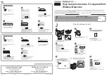
Step 1: Prepare the Site for MX104 Router Installation . . . . . . . . . . . . . . . . . . . . . . . 4
Step 2: Install the Router . . . . . . . . . . . . . . . . . . . . . . . . . . . . . . . . . . . . . . . . . . . . . . 6

Tools Required to Install the Router in a Rack . . . . . . . . . . . . . . . . . . . . . . . . . . 6
Install the MX104 Router in the Rack 
. . . . . . . . . . . . . . . . . . . . . . . . . . . . . . . . . 6

Step 3: Ground the MX104 Router . . . . . . . . . . . . . . . . . . . . . . . . . . . . . . . . . . . . . . . 8

Tools Required to Ground the MX104 Router . . . . . . . . . . . . . . . . . . . . . . . . . . . 8
Connect the Grounding Cable 
. . . . . . . . . . . . . . . . . . . . . . . . . . . . . . . . . . . . . . 8

Step 4: Connect External Devices and Cables . . . . . . . . . . . . . . . . . . . . . . . . . . . . . 10

Connect the Router to a Network for Out-of-Band Management . . . . . . . . . 10
Connect the Router to a Management Console Device 
. . . . . . . . . . . . . . . . . . 10
Connect MIC Cables to the MX104 Router . . . . . . . . . . . . . . . . . . . . . . . . . . . . . 11

Step 5: Connect Power to the MX104 Router . . . . . . . . . . . . . . . . . . . . . . . . . . . . . . 13

Connect AC Power to an AC-Powered MX104 Router . . . . . . . . . . . . . . . . . . . 13
Connect DC Power to a DC-Powered MX104 Router . . . . . . . . . . . . . . . . . . . . 14

Step 6: Perform Initial Software Configuration . . . . . . . . . . . . . . . . . . . . . . . . . . . . 18

Enter Configuration Mode . . . . . . . . . . . . . . . . . . . . . . . . . . . . . . . . . . . . . . . . . 18
Configure User Accounts and Passwords 
. . . . . . . . . . . . . . . . . . . . . . . . . . . . . 18
Configure System Attributes . . . . . . . . . . . . . . . . . . . . . . . . . . . . . . . . . . . . . . . 19
Commit the Configuration 
. . . . . . . . . . . . . . . . . . . . . . . . . . . . . . . . . . . . . . . . . 19

Safety Warnings . . . . . . . . . . . . . . . . . . . . . . . . . . . . . . . . . . . . . . . . . . . . . . . . . . . . 21
Compliance Statements for NEBS . . . . . . . . . . . . . . . . . . . . . . . . . . . . . . . . . . . . . 22
Compliance Statements for EMC Requirements 
. . . . . . . . . . . . . . . . . . . . . . . . . . 22

Canada . . . . . . . . . . . . . . . . . . . . . . . . . . . . . . . . . . . . . . . . . . . . . . . . . . . . . . . 23
European Community 
. . . . . . . . . . . . . . . . . . . . . . . . . . . . . . . . . . . . . . . . . . . . 23
Israel 
. . . . . . . . . . . . . . . . . . . . . . . . . . . . . . . . . . . . . . . . . . . . . . . . . . . . . . . . . 23
Japan 
. . . . . . . . . . . . . . . . . . . . . . . . . . . . . . . . . . . . . . . . . . . . . . . . . . . . . . . . . 23
United States 
. . . . . . . . . . . . . . . . . . . . . . . . . . . . . . . . . . . . . . . . . . . . . . . . . . . 23

1

Copyright © 2016, Juniper Networks, Inc.

Summary of Contents for MX104 3D

Page 1: ...ct External Devices and Cables 10 Connect the Router to a Network for Out of Band Management 10 Connect the Router to a Management Console Device 10 Connect MIC Cables to the MX104 Router 11 Step 5 Connect Power to the MX104 Router 13 Connect AC Power to an AC Powered MX104 Router 13 Connect DC Power to a DC Powered MX104 Router 14 Step 6 Perform Initial Software Configuration 18 Enter Configurati...

Page 2: ... and Release Notes 24 Requesting Technical Support 24 Self Help Online Tools and Resources 24 Opening a Case with JTAC 25 Revision History 25 Copyright 2016 Juniper Networks Inc 2 MX104 3D Universal Edge Routers Quick Start ...

Page 3: ... 55 cm tall Several routers can be stacked in a single floor to ceiling rack for increased port density per unit of floor space The chassis installs in standard 11 81 in 30 cm deep or larger enclosed cabinets 19 in equipment racks or telco open frame racks Figure 1 Front View of the MX104 Router g007602 17 16 15 13 14 12 3 1 5 4 10 11 9 8 7 6 2 9 1 ESD point Alarm input and output contacts 10 2 Gr...

Page 4: ... of the chassis and any non heat producing surface such as a wall For service personnel to remove and install hardware components there must be adequate space at the front and back of the router Allow at least 30 in 76 2 cm in front of the router and 24 in 61 cm behind the router The rack or cabinet must have an adequate supply of cooling air Ensure that the cabinet allows the chassis hot exhaust ...

Page 5: ...Figure 2 MX104 Rack Clearance and Chassis Dimensions 5 Copyright 2016 Juniper Networks Inc Step 1 Prepare the Site for MX104 Router Installation ...

Page 6: ... building Ensure that the installation site allows adequate clearance for both airflow and maintenance 2 Position the router in front of the rack or cabinet 3 Have one person grasp both sides of the router lift the router and position it in the rack aligning the mounting bracket holes with the threaded holes in the rack rails Make sure the chassis is level 4 Have the second person install a mounti...

Page 7: ...Figure 3 Installing the Front Mounted Router in the Rack 3 1 Mounting screws Rack 2 MX104 router 7 Copyright 2016 Juniper Networks Inc Install the MX104 Router in the Rack ...

Page 8: ...ding point See the instructions for your site 3 Ensure that all grounding surfaces are clean and brought to a bright finish before grounding connections are made 4 Connect the grounding cable to a proper earth ground 5 Detach the ESD grounding strap from the site ESD grounding point 6 Attach an ESD grounding strap to your bare wrist and connect the strap to one of the ESD points on the chassis 7 P...

Page 9: ...re that the driver is undamaged and properly calibrated and that you have been trained in its use You may wish to use a driver that is designed to prevent overtorque when the preset torque level is achieved 9 Dress the grounding cable and verify that it does not touch or block access to router components and that it does not drape where people could trip on it Figure 4 Grounding Points on the MX10...

Page 10: ...her end of the cable into the network device Figure 5 Ethernet Cable Connector Figure 6 Ethernet Port g006425 Management PC MGMT port Management network Connect the Router to a Management Console Device 1 Turn off the power to the console or auxiliary device 2 Plug the RJ 45 end of the serial cable into the CONSOLE port on the Routing Engine Figure 7 on page 11 shows the connector Figure 8 on page...

Page 11: ...cap keeps the port clean and prevents accidental exposure to laser light 3 Insert the cable connector into the cable connector port on the faceplate NOTE TheXFPcagesandopticsonthecomponentsareindustrystandard parts that have limited tactile feedback for insertion of optics and fiber You need to insert the optics and fiber firmly until the latch is securely in place 4 Use the equipment frame to sup...

Page 12: ...ber optic cable hang free from the connector Do not allow fastened loops of cable to dangle which stresses the cable at the fastening point Copyright 2016 Juniper Networks Inc 12 MX104 3D Universal Edge Routers Quick Start ...

Page 13: ...sert the appliance coupler end of the power cord into the appliance inlet on the power supply 4 Insert the power cord plug into an external AC power source receptacle NOTE Each power supply must be connected to a dedicated AC power feed and a dedicated customer site circuit breaker We recommend that you use a dedicated customer site circuit breaker rated for 10 A 100 VAC or as required by local co...

Page 14: ... or as required by local code not provided DC power ring lugs Panduit PV12 14HDRB 2k two per DC power supply M6 screws and washers two per DC power supply attached Grounding cable use 6 AWG 13 3 mm 2 60 C wire for 24V DC not provided The DC power supply has two terminals on each power supply covered by a clear plastic cover Table 1 MX104 DC Power System Input Voltage Specification Nominal Voltage ...

Page 15: ...d to chassis ground at the battery plant you can use a multimeter to verify the resistance of the 48V and return DC cables to chassis ground For 48V and 60V a The cable with very high resistance indicating an open circuit to chassis ground is the DC input cable b The cable with very low resistance indicating a closed circuit to chassis ground is the return cable For 24V a The cable with very low r...

Page 16: ... less Ensure that the driver is undamaged and properly calibrated and that you have been trained in its use You may wish to use a driver that is designed to prevent overtorque when the preset torque level is achieved 7 Replace the plastic cover over the terminals on the faceplate 8 Connect each DC power cable to the appropriate external DC power source NOTE For information about connecting to exte...

Page 17: ...Figure 11 Connecting a DC Power Cable to an MX104 DC Power Supply 17 Copyright 2016 Juniper Networks Inc Connect DC Power to a DC Powered MX104 Router ...

Page 18: ...ot 4 Enter configuration mode cli configure edit root Configure User Accounts and Passwords For information about using an encrypted password or an SSH public key string DSA or RSA see the Junos OS Administration Library for Routing Devices 1 Add a password to the root administration user account Enter a clear text password edit root set system root authentication plain text password New password ...

Page 19: ...es to remote subnets with access to the management port Access to the management port is limited to the local subnet To access the management port from a remote subnet you need to add a static route to that subnet within the routing table For more information about static routes see the Junos OS Administration Library for Routing Devices edit root set routing options static route remote subnet nex...

Page 20: ...onal Configure additional properties by adding the necessary configuration statements Then commit the changes to activate them on the router edit root host commit 4 When you have finished configuring the router exit configuration mode edit root host exit root host Copyright 2016 Juniper Networks Inc 20 MX104 3D Universal Edge Routers Quick Start ...

Page 21: ...re wrist Failure to use an ESD strap could result in damage to the router CAUTION Use an external surge protective device SPD at the AC input of the router Only trained and qualified personnel should install or replace the router Perform only the procedures described in this Quick Start or the MX104 3D Universal Edge Router Hardware Guide Other services should be performed by authorized service pe...

Page 22: ...esult in serious physical injury AC power cable warning Japan WARNING The attached power cable is only for this product Do not use the cable for another product Compliance Statements for NEBS The equipment is suitable for installation as part of the Common Bonding Network CBN The equipment is suitable for installation in locations where the National Electrical Code NEC applies The battery return c...

Page 23: ...ct is used near a radio or television receiver in a domestic environment it might cause radio interference Install and use the equipment according to the instruction manual VCCI A United States The hardware equipment has been tested and found to comply with the limits for a Class A digital device pursuant to Part 15 of the FCC Rules These limits are designed to provide reasonable protection agains...

Page 24: ...s en local pdf resource guides 7100059 en pdf Product warranties For product warranty information visit http www juniper net support warranty JTAC Hours of Operation The JTAC centers have resources available 24 hours a day 7 days a week 365 days a year Self Help Online Tools and Resources For quick and easy problem resolution Juniper Networks has designed an online self service portal called the C...

Page 25: ...ion January 2015 530 062013 Revision 1 Minor updates November 2013 530 053224 Revision 1 Initial release Copyright 2016 Juniper Networks Inc All rights reserved Juniper Networks Junos Steel Belted Radius NetScreen and ScreenOS are registered trademarks of Juniper Networks Inc in the United States and other countries The Juniper Networks Logo the Junos logo and JunosE are trademarks of Juniper Netw...

Reviews: