junger D*AP4 VAP Edition, Manual
The junger D*AP4 VAP Edition is a state-of-the-art audio processor designed for broadcast professionals. Enhance your audio quality with this versatile device. For detailed instructions on how to maximize its features, download the free user manual from manualshive.com. Get the most out of your equipment with this essential manual.
Share
Download


Reviews:
No comments
Related manuals for D*AP4 VAP Edition

Ceiling Trim Kit for Home2 Series
Brand: Elite Screens Pages: 8

ClickShare CSC-1
Brand: Barco Pages: 3

BDM-610000075
Brand: rtd Pages: 120

KMD3102W
Brand: Beko Pages: 116
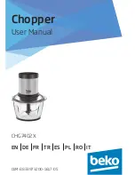
CHG7402X
Brand: Beko Pages: 124

CHG6400W
Brand: Beko Pages: 100

CHG7504W
Brand: Beko Pages: 84

CHP7504W
Brand: Beko Pages: 85

FPP 4102 W
Brand: Beko Pages: 66

CHP6450W
Brand: Beko Pages: 92

CHP5550W
Brand: Beko Pages: 136

CHP5554W
Brand: Beko Pages: 136

KW-4605
Brand: KYOWA Pages: 3
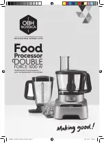
Double Force
Brand: OBH Nordica Pages: 24

canalettoHDi
Brand: Eyeheight Pages: 2

Integrated Transport & Processor KPS-30i
Brand: Krell Industries Pages: 17

VLMC101-H
Brand: VivoLink Pages: 8

VT-1639
Brand: Vitek Pages: 24


