JUKI LZ-2290A/IP-110A/SC-915, Instruction Manual
The JUKI LZ-2290A/IP-110A/SC-915 is a versatile and high-performance sewing machine. To help you unleash its full potential, an easy-to-follow Instruction Manual is available for download. Get your free manual from manualshive.com, and unlock all the features and tips needed to make every sewing project a success.
Share
Download


Reviews:
No comments
Related manuals for LZ-2290A/IP-110A/SC-915
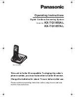
KX-TG1855AL
Brand: Panasonic Pages: 44
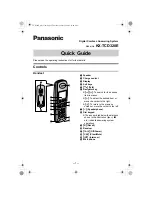
KX-TCD320E
Brand: Panasonic Pages: 6
KX-TCD240E
Brand: Panasonic Pages: 8
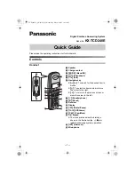
KX-TCD220G
Brand: Panasonic Pages: 6

TOYBOX
Brand: UNIS Pages: 19
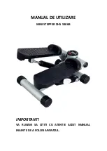
DHS 5306B
Brand: DHS Fitness Pages: 9

BX2 Fastracts Extractor
Brand: IPC Eagle Pages: 8

fs288
Brand: Feiyue Pages: 11

KM 70/30 C Bp
Brand: Kärcher Pages: 28

2030DC
Brand: Janome Pages: 44

Citymaster 2000
Brand: HAKO Pages: 186

GF-1117 Series
Brand: Garudan Pages: 30

Memory Craft 550E
Brand: Janome Pages: 84

MC S6 B
Brand: Racing Pages: 22

FM43 ORBITALE
Brand: Fimap Pages: 56

F-43N
Brand: Uchida Yoko Pages: 25
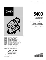
5400
Brand: Tennant Pages: 155

AquaRide 56314009
Brand: Nilfisk-Advance Pages: 32


