JUKI HZL-G Series, Service Manual
The JUKI HZL-G Series is a high-performance sewing machine designed for professional use. With advanced features and intuitive controls, this user-friendly machine ensures flawless stitching. Enhance your sewing experience by easily accessing the free service manual for the JUKI HZL-G Series, available for download from manualshive.com.
Share
Download


Reviews:
No comments
Related manuals for HZL-G Series

S750
Brand: Janome Pages: 41

ambition essential
Brand: Pfaff Pages: 36

EWF-E7152D
Brand: Elba Pages: 17

GARUDAN GF-1107-147 MH
Brand: Anita Pages: 73

Clarke Encore L26 Cylindrical
Brand: Alto Pages: 32

HCS2-1201
Brand: Happy Pages: 15

Cadet 10080050
Brand: Windsor Pages: 23

LAVINA ELITE L30LEU
Brand: Superabrasive Pages: 40

C210
Brand: GBC Pages: 38

PRESTO
Brand: Baby Lock Pages: 128
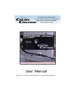
Quilter's Cruise Control Voyager 17
Brand: Hinterberg Design Pages: 3

2802
Brand: Singer Pages: 48

LK-980 Series
Brand: JUKI Pages: 52

SE200-M SERIES
Brand: Suzuki Pages: 29

10
Brand: Kenmore Pages: 90

GHID-800E
Brand: Brother Pages: 20

HE-240
Brand: Brother Pages: 40

HS-2500
Brand: Brother Pages: 2


