JUKI APW-896/IP-420, Instruction Manual
The JUKI APW-896/IP-420 is a powerful and versatile sewing machine designed for professional use. To ensure seamless operation and optimal results, it comes with a comprehensive Instruction Manual. Download this manual for free on our website, manualshive.com, and unlock the full potential of your JUKI sewing machine.
Share
Download


Reviews:
No comments
Related manuals for APW-896/IP-420

34
Brand: R.P.S. Corporation Pages: 23

HQ Sweet Sixteen
Brand: handi quilter Pages: 30

Coverstyle
Brand: Pfaff Pages: 68

CHARGER 2022 ABLT
Brand: NSS Pages: 16

RHINO RD 160
Brand: ROOTS Pages: 164

FX 700
Brand: JB Systems Pages: 14

253-200
Brand: Singer Pages: 25
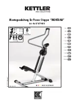
MONTANA
Brand: Kettler Pages: 36

2-9824
Brand: GE Pages: 18

2-9868
Brand: GE Pages: 20

2-9866
Brand: GE Pages: 2

15638680 (REV. 1 E/S) 29878
Brand: GE Pages: 2

16018110
Brand: GE Pages: 2

2 2-9992 2-9992
Brand: GE Pages: 32

16174120
Brand: GE Pages: 48

29869 Series
Brand: GE Pages: 56

2-8111A
Brand: GE Pages: 84

2-9801
Brand: GE Pages: 1


