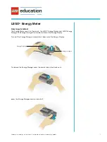
Gyro Amp
LED Red/Green Mode Indicator
Tail Lock On/Off Switch
Connector
to Gyro Sensor
Rev. Switch
Servo
Connector
Connect to
SV
Gyro Sensor
JR 4735 Standard Analog
JR 8700G Super Servo
or 8417 Digital Servo
Rudder Connector
Connect to RUDD
Rate/Tail Lock
Remote Select
Aux 3 Connector
(white)
Receiver
G 5 5 0 T
A D VANCED TAIL LOCK
™
GYRO SYSTEM
I N S T R U C T I O N S
J R P G 5 5 0 T
For Helicopter use only
For use with JR Standard, Super
or Digital Ser v o s .
F E AT U R E S
• Advanced Tail Lock: The G550T features both a normal “rate” mode, as well as an
“Advanced tail lock” mode. The advanced tail lock mode is designed to provide the
3D pilot with a high-perf o rmance heading hold system.
• Rate Mode: The G550T’s design is based from the previous G1000 and G900,
which are known world over for their perf o rmance and re l i a b i l i t y.
• S e rv o s : The G550T is designed for use with JR’s Standard Servos as well as
8700G Super or 8417 Digital Serv o s .
• O ffset drift canceling: C i rc u i t ry for superior neutral stability.
• Remote gain contr o l : P rovides remote adjustment of the gain values, as well as
access to rate and tail lock modes.
• Lightweight Piezo sensor w/ dampening: New double action suspension dampen-
ing and lightweight Piezo crystal — total sensor weighs only 18 grams!
• Compatible with all JR, Futaba
®
and other radio systems.
S P E C I F I C AT I O N S
Operating Voltage: 4.8V only
Operating Current: 50mA (not including serv o )
D i m e n s i o n s
G y ro Sensor: 32 x 30 x 36 mm
Amplifier: 38 x 19 x 53 mm
We i g h t
G y ro Sensor: 18 grams
Amplifier: 33 grams
Total Weight: 51 grams (1.8 o.z.)
I N T R O D U C T I O N
J R ’s new advanced G550T is based on JR’s outstanding G1000 and G900 the
G550T incorporates the same rate gyro technology, while adding the new “advanced
tail lock” heading hold mode. This new “tail lock” mode has been designed to pro-
vide the 3D Helicopter pilot with a heading hold system that will allow the pilot to
push both their flying skills, as well as their equipment to the limits.
S E RVO SELECTION
J R ’s G550T can be used in conjunction with JR’s Standard Analog servos 4735,
8700G Super Servo or 8417 Digital servos. These servos feature an ultra-quick
response and transit time and are specifically matched to give the best possible re s-
olution when used with the G550T.
HELICOPTER TAIL ROTOR SYSTEM
I m p o rtant: Because of the highly active/aggressive characteristics of this G550T,
h e a v i e r- t h a n - n o rmal loads are placed on the tail rotor drive train. Ensure that the
main drive gear system and tail rotor gear box is in good working order with the
c o rrect gear mesh and unworn teeth. Also be sure it’s properly greased with all
s c rews secured with Locktite
®
, etc.
On Miniature Aircraft X-Cell helicopters, a heavy-duty front tail rotor tune-up kit is
recommended (part # MIN0832). When using the G550T in a JR belt-driven tail
rotor helicopter, such as the Ergo 60 or Vi g o r, it’s recommended that the optional JR
aluminum tail pulleys be installed for maximum perf o rmance (JRP960322 fro n t ,
JRP960323 rear). The use of aluminum pulleys will greatly reduce tail belt slippage
as compared to the standard plastic pulleys. It’s recommended that the tail belt be
checked after each flying session. If worn or missing teeth are discovered, re p l a c e
the tail belt as needed.
Note: The G550T SHOULD NOT be installed in a model that utilizes a “PIANO
WIRE” tail drive system, as failure can occur.
MAXIMIZING THE G550T
N o t e : The G550T Piezo Gyro ’s operational features and functions are very diff e r-
ent from other types of gyros. The adjustments, including travel adjust, exponential,
dual rates, tail rotor compensation values and gain values will be very diff e rent fro m
your previous normal settings. Do not install the G550T in your helicopter using
your current set up. The capabilities of this gyro are much greater; there f o re, the
adjustment values will be diff e rent, and you must adjust them correctly to realize the
s y s t e m ’s full potential.
C a refully read this instruction manual and be sure you fully understand and fol-
low each segment before your first flight.
I N S TA L L ATION
When deciding where to mount the gyro sensor, consider the criteria below:
Vibration
Because vibration is motion, the G550T Gyro senses even minute vibrations and
acts upon them, sending the rudder servo an opposing command. For optimum
results, it’s imperative that your helicopter is as vibration-free as possible. All ro t a t-
ing components (e.g., main gear, head, tail ro t o r, blades, clutch, etc.) should be in
p e rfect balance. Equally important, the engine should run smoothly and consistently.
Spending the extra time to ensure that your machine is running perfectly will allow
the gyro gain to be turned up higher, more effectively holding the tail.
Temperatur e
The Piezo sensor is sensitive to drastic changes in temperature. Note that the
case features a matte chrome finish that is designed to reflect heat. When mounting
the gyro sensing unit, be sure that it’s located away from the engine and exhaust
system so the heat does not transfer to the sensing unit. Also, when subjecting your
helicopter to temperature changes (e.g., going from your warm car to the cold out-
doors), allow the gyro ’s temperature to stabilize for about 10 minutes before flying.
Installing the Gyro Sensor
T h o roughly clean the bottom of the gyro sensor and the mounting area with ru b-
bing alcohol. Use one layer of the supplied double-sided tape to securely mount the
sensor in position.
N o t e : Do not use thick foam tape or multiply layers of double-sided tape as is
common practice with other gyros. The G550T’s sensor is vibration/shock mounted
inside its case via a rubber/air dampening system, and no further vibration isolation
is necessary.
Installing the Amplifier
Using the 1/4” or thicker foam, wrap the amplifier and the receiver together, mak-
ing sure that at least one thickness of foam is between the receiver and amplifier.
Fasten the receiver and amplifier to the radio tray using rubber bands, making sure
they are securely held in place. If space restrictions don’t permit the amplifier and
receiver to be mounted together, wrap them individually in foam and mount each in
a convenient location. Use an optional servo extension lead if necessary.
C O N N E C T I O N S
Step 1: On the gyro amplifier, locate the lead marked “RU D D”. Connect this lead to
the rudder channel in the re c e i v e r.
Step 2: On the amplifier, locate the lead marked “AU X 3.” Note that it has a white
connector for identification. When using a JRPCM-10, 10S, 10SX, 10SXF or 10X
radio system, connect this lead to the Aux 3-channel in the re c e i v e r. For JR 8103
systems, connect this lead to the Aux 2-channel.
Note: When using this gyro with other radios, like the JRXP652, the Aux 3 lead
must be connected to the appropriate channel — the one you use to alter the gain.
For example, if you want to use the gear switch to alter the gain, plug the Aux 3 lead
into the gear channel and use the travel adjust and sub-trim function to achieve the
d e s i red gain in both switch positions.