background image

NAE55 Installation Guide

Application

The Metasys Network Automation Engine (NAE) is an

Ethernet-based, supervisory device that connects BAS

networks to IP networks. NAEs monitor and control

field-level building automation devices, including HVAC

equipment, lighting, security, and fire safety equipment.

At Release 11.0, the NAE55 is also FIPS 140-2 Level 1

compliant. FIPS 140-2 is a United States government

cybersecurity standard that approves cryptographic

modules/algorithms used for encryption. Use this

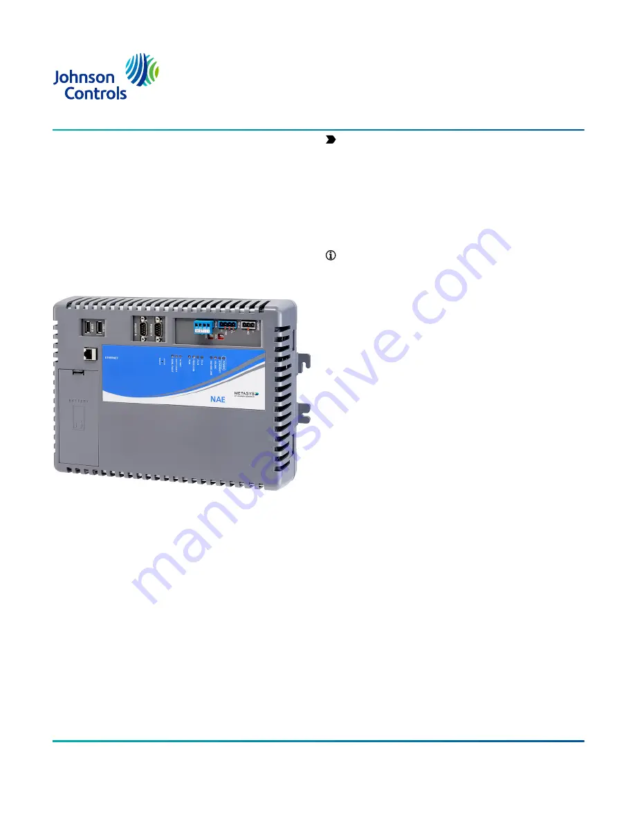
document to install the NAE. Figure 1 shows the NAE55

engine.

Figure 1: NAE55 Network Engine

The NAE offers various integration options. Ethernet

network integrations include the following options:
• Johnson Controls and 3rd party BACnet/IP, BACnet/SC

devices

• Simplex

®

 Fire Alarm Control Unit (FACU)

• Cree

®

 SmartCast

®

 Lighting Control

• Molex

®

 Lighting Control

• Tyco

®

 C•CURE

®

 9000 or victor

®

 Video Management

• Modbus TCP/IP

• KNX IP

• OPC UA integration at Metasys Release 11.0
Field Bus integrations include the following options:
• BACnet MS/TP

• N2 Bus

• LonWorks

®

 (NAE552x models only)

• Modbus Remote Terminal Unit (RTU)

• Meter Bus (M-Bus)

• Zettler

®

 Fire Panel

Important: 

For any other custom integrations,

contact your local Systems Integration Services

(SIS) team before an upgrade. Updated drivers are

available on request.

In this installation guide, the term network engine

applies to any NAE55 model, unless otherwise stated.

For installation instructions on the NAE55s that are

approved for Metasys system smoke control applications,

refer to the 

NAE55 Installation Instructions (Part No.

24-10051-00132)

.

Note: 

At Metasys Release 10.0 and later, modems

(internal and external) and pagers are no longer

supported on NAE55 engines that run the Linux

operating system, but are still supported on

prior releases for engines that use a Windows

Embedded operating system. You can field-upgrade

a network engine at Release 9.0 that has an internal

modem to Release 10.0 or later to acquire new

release enhancements, but its modem and pager

functionality are lost. If you need modem and pager

functionality, do not upgrade the NAE55 engine to

Release 10.0 or later.

Installation

Follow these guidelines when installing the network

engine:
• Transport the network engine in the original container

to minimize vibration and shock damage to the network

engine.

• Verify that all the parts shipped with the network

engine. The data protection battery and network engine

ship together but are packaged separately.

• Do not drop the network engine or subject it to physical

shock.

• Do not open the network engine housing (except the

data protection battery compartment). The network

engine has no user-serviceable parts inside.

Parts included

• one MS-NAE55xx-x model

• one data protection battery

• one installation instructions sheet

Materials and special tools needed

You can mount the network engine by using the fasteners

option or the DIN rail option.
• Fasteners option - Three fasteners appropriate for the

mounting surface:

- #8 screws - North America

- M4 screws - Europe

• DIN rail option - 36 cm (14 in.) or longer section of 35

mm (1 1/8 in.) for DIN rail mount applications only.

*241005143W*

Part No. 24-10051-43 Rev. W

Release  12.0

2022-05-20

(barcode for factory use only)

MS-NAE5510-3, MS-NAE5510-3U, MS-NAE5520-3

Summary of Contents for Metasys NAE55

Page 1: ... NAE55 Installation Instructions Part No 24 10051 00132 Note At Metasys Release 10 0 and later modems internal and external and pagers are no longer supported on NAE55 engines that run the Linux operating system but are still supported on prior releases for engines that use a Windows Embedded operating system You can field upgrade a network engine at Release 9 0 that has an internal modem to Relea...

Page 2: ...ation Figure 6 Mount the network engine on an even surface in wall mount applications whenever possible If you must mount the network engine on an uneven surface be careful not to crack the wall mount feet or housing when tightening the screws Use shims or washers to mount the unit securely on the mounting surface Mount the network engine in areas free of corrosive vapors and observe the environme...

Page 3: ... the network engine on the screws with the upper two mount feet Figure 6 5 Insert the screws into the lower two wall mount feet and holes and carefully tighten all of the screws Important Do not overtighten the mounting screws Overtightening the screws can crack the network engine wall mount feet or housing Mounting the Network Engine for DIN rail mount applications To mount the network engine on ...

Page 4: ...not connected to any earth ground connection The FC A and FC B terminal blocks are not interchangeable LonWorks network terminal block The LonWorks TP FT 10 network connection available only on the network engine LonWorks model is a 3 wire removable keyed terminal block The Shield connection on the LonWorks network terminal block is an isolated terminal and is not connected in the network engine U...

Page 5: ...s may result in permanent damage to the equipment Do not apply 24 VAC power to the network engine before installing the data protection battery See the Installing the data protection battery section in this document Use copper conductors only Make all wiring in accordance with local national and regional regulations The network engine is a low voltage 30 VAC device Do not exceed the network engine...

Page 6: ...ed shield connection terminal 3 Set each FC EOL switch to their proper positions See the note in Setting the end of line switches Connecting LonWorks devices About this task To connect LonWorks devices complete the following steps 1 Connect the 2 wire cable from the LonWorks trunk to the removable 3 terminal blue plug labeled LON Figure 3 The LonWorks network trunk is available on the MS NAE5520 3...

Page 7: ...converter s A terminal to the device s or A terminal b Connect the converter s B terminal to the device s or B terminal Figure 11 Connection between converter and device 4 To add additional vendor devices wire from one device to the next in a daisy chain configuration The completed wiring should look similar to Figure 12 Figure 12 Modbus RTU wiring detail overview Connecting M Bus devices About th...

Page 8: ...D receive data PIN 3 on RJ12 7 GND ground PIN 5 on RJ12 4 To network engine RS 232C port Connecting KNX devices About this task The network engine connects to a KNX network device by using the KNX IP interface router After installation and wiring are complete refer to the Network Engine Commissioning for KNX Vendor Integration Application Note LIT 12013148 for additional information 1 Connect an E...

Page 9: ...e removable power terminal connector on the network engine Figure 15 The connections are HOT and COM common Do not apply power yet Figure 15 Supply power wiring 24 VAC transformer Table 8 Power supply wiring Callout Description 1 NAE power terminal block 2 NAE power terminal block plug 3 Terminating wire for 24 VAC orange 4 Terminating wire for Common brown 5 Terminating wires from 24 VAC Class 2 ...

Page 10: ...ly 3 minutes to start up and become operational See the LED test sequence at startup section Startup is complete and the network engine is operational when the green RUN LED is On steady and the red GEN FAULT LED is Off See Figure 18 for LED locations Disconnecting power from the Network Engine Important The data protection battery must be installed and charged before disconnecting the 24 VAC supp...

Page 11: ...lished at 100 Mbps On Steady Yellow Ethernet connection is established at 1 000 Mbps FC A Green Flicker On Steady Controllers are defined to FC A FC Bus 1 or N2 Trunk 1 in the network engine but none are communicating network engine transmitting only Flicker Normal communications FC A port is transmitting and receiving data Flickers are generally in sync with data transmission but should not be us...

Page 12: ...tegory Rules and Maximums General Star topology with network switches Number of Devices Maximum of 1 000 devices permitted at one site in the Metasys network 2 000 m 6 600 ft for plastic glass fiber optic with external adapter Line Length and Type 10 BaseT 100 m 330 ft Cat5 or Cat6 cable 100 BaseT 100 m 330 ft Cat5 or Cat6 cable 1000 BaseT 100 m 330 ft Cat5E or Cat6 cable Terminations For 10 100 1...

Page 13: ...imally Required Termination Configuration At least one N2 device with an EOL switch in the ON position somewhere on each N2 Bus segment Table 14 Modbus RTU rules Category Rules and Maximums General One direct Modbus RTU RS 232 connection to either RS232C port is supported connection requires an RS 232 RS 485 converter to the RS232C serial port One direct Modbus RTU RS 485 connection to either FC B...

Page 14: ... 2 x 0 8 mm 20 AWG shielded resistance 30 Ohms 64 350 m 1 148 ft 4 000 m 13 123 ft 2 x 0 8 mm 20 AWG shielded resistance 30 Ohms 9 600 250 350 m 1 148 ft 1 000 m 3 281 ft 2 x 0 8 mm 20 AWG shielded resistance 30 Ohms 38 400 64 350 m 1 148 ft 1 000 m 3 281 ft 2 x 0 8 mm 20 AWG shielded resistance 30 Ohms Line Length and Type Cable Twisted pair cable shielding optional Termination No termination 1 U...

Page 15: ... 700 m 8 850 ft 2 200 m 7 200 ft Belden 8471 Cable 2 700 m 8 850 ft 2 200 m 7 200 ft Level IV 22 AWG 1 400 m 4 600 ft 1 150 m 3 770 ft JY St Y 2 x 2 x 0 8 900 m 2 950 ft 750 m 2 460 ft Note For the bus topology the maximum length stub cable is 3 m 10 ft and the stub lengths must be calculated into the overall segment length 1 FTT Free Topology Twisted Pair Transceiver LPT Link Power Twisted Pair T...

Page 16: ...g mode Repair information If you replace a network engine for any reason or add a new network engine to a site you must update the site registration to ensure that the new network engine is recognized and able to communicate on the Metasys system site For details refer to the Replacing an NAE section in the NAE Commissioning Guide LIT 1201519 Except for replacing the data protection battery the ne...

Page 17: ... a LonWorks trunk two third party trunks Modbus RTU or TCP M Bus or KNX or two N2 trunks BACnet MS TP RS 485 trunks or one N2 trunk and one BACnet MS TP trunk Supports up to 255 devices on the LonWorks trunk Supports up to 100 devices on each N2 or BACnet MS TP trunk Supports a BACnet IP or BACnet SC network This model is a BACnet BTL Listed controller at protocol revision 15 PR15 Table 23 Network...

Page 18: ... IP router to connect KNX line through Ethernet to a network engine including line or area coupler functionality Note Order these accessories in AOMS from the European Distribution Center Note When you use the GRIPIN01 S KNX for NAE integration use a non secure mode Set Metasys driver N ROUTING MODE and in ETS set Secure mode to deactivated Table 27 Modbus training tool ordering information Course...

Page 19: ...c housing with internal metal shield Plastic material ABS polycarbonate Protection IP20 IEC 60529 Mounting On a flat surface with screws on four mounting feet or on a dual 35 mm DIN rail Dimensions Height x Width x Depth 226 mm x 332 mm x 96 5 mm or 8 9 in x 13 1 in x 3 8 in including mounting feet Minimum space for mounting 303 mm x 408 mm x 148 mm or 12 0 in x 16 1 in x 5 8 in Shipping weight 2 ...

Page 20: ...s all the requirements of the Canadian Interference Causing Equipment Regulations Cet appareil numérique de la Classe A respecte toutes les exigences du Règlement sur le matériel brouilleur du Canada Industry Canada Statement s This device complies with Industry Canada licence exempt RSS standard s Operation is subject to the following two conditions 1 This device may not cause interference and 2 ...

Reviews: