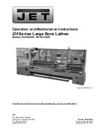


Operation and Maintenance Instructions
ZH Series Large Bore Lathes
Models GH-2680ZH; GH-26120ZH
Model GH-2680ZH shown
For ZH-Series Lathes Parts List and Electrical Diagrams, see document M-321860-1
JET
427 New Sanford Road
LaVergne, Tennessee 37086
Part No. M-321860
Ph.: 800-274-6848
Revision C3 08/2018
www.jettools.com
Copyright © 2017 JET
Summary of Contents for ZH Series
Page 34: ...34 18 0 Change Gear Diagram Figure 54...
Page 35: ...35 This page intentionally left blank...
Page 40: ...4 1 1 Bed Assembly I Exploded View...
Page 41: ...5 1 2 Bed Assembly I for 120 ZH only Exploded View...
Page 44: ...8 2 1 Bed Assembly II Exploded View...
Page 45: ...9 2 2 Bed Assembly II for 120 ZH only Exploded View...
Page 48: ...12 3 1 Headstock Assembly I Exploded View b b Z Z Z...
Page 51: ...15 4 1 Headstock Assembly II Exploded View...
Page 54: ...18 5 1 Headstock Assembly III Exploded View...
Page 56: ...20 6 1 Headstock Assembly IV Exploded View b...
Page 59: ...23 7 1 Headstock Assembly V Exploded View b...
Page 62: ...26 9 1 Gear Box Assembly I Exploded View...
Page 64: ...28 10 1 Gear Box Assembly II Exploded View...
Page 67: ...31 11 1 Gear Box Assembly III Exploded View...
Page 70: ...34 12 1 Brake Assembly Exploded View...
Page 72: ...36 13 1 Saddle and Cross Slide Assembly Exploded View...
Page 75: ...39 14 1 Tool Post and Compound Rest Assembly Exploded View...
Page 77: ...41 15 1 Apron Assembly I Exploded View...
Page 80: ...44 16 1 Apron Assembly II Exploded View...
Page 83: ...47 17 1 Apron Assembly III Exploded View...
Page 85: ...49 18 1 Apron Assembly IV Exploded View...
Page 87: ...51 19 1 Tailstock Assembly I Exploded View...
Page 89: ...53 20 1 Tailstock Assembly II Exploded View...
Page 91: ...55 21 1 Steady Rest Assembly Small and Large Exploded View...
Page 95: ...59 24 1 Travel Stop Assembly Exploded View...
Page 100: ...64 27 2 Electrical Diagram...