background image

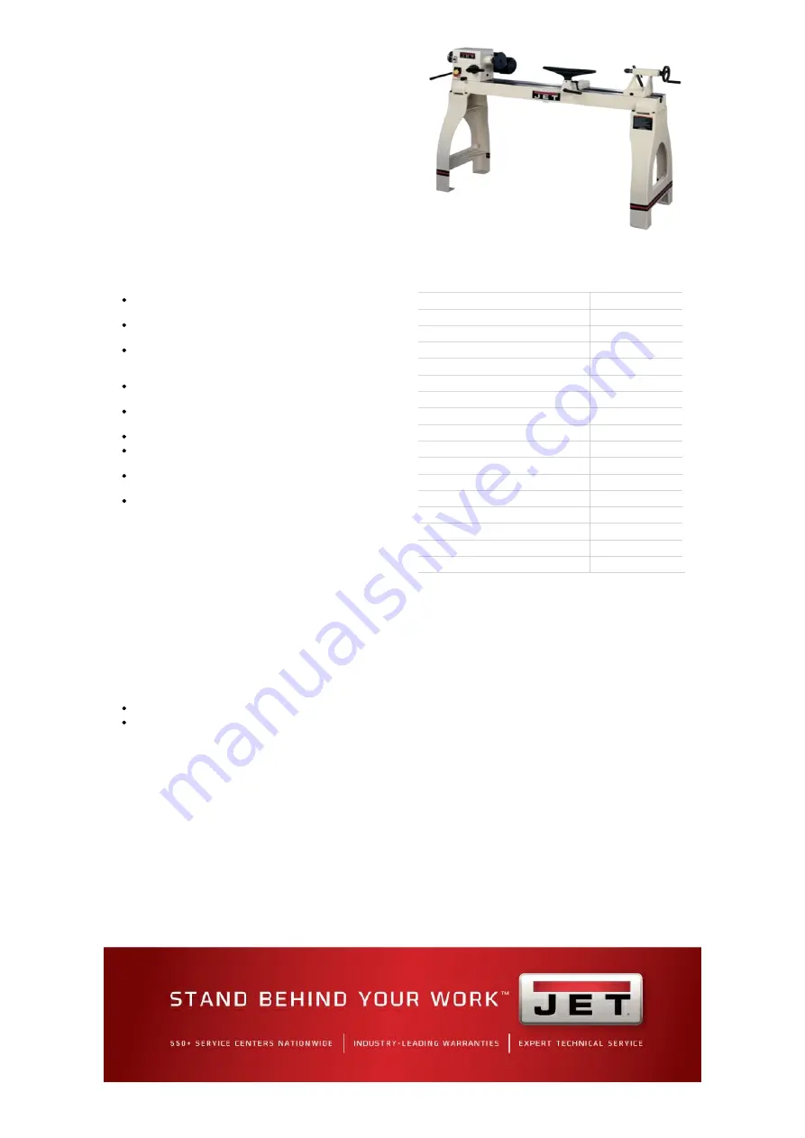
JWL-1442VSK, 14" X 42" VS
PRO WOOD LATHE WITH
LEGS

708358K

This mid range lathe offers mechanical variable speed along with a

headstock that pivot as well as slide to the end of the bed for

outboard turning capabilities

FEATURES

Reeves drive pulley system allows quick variable speed
changes from 450 to 3,000 RPM 

Heavy-duty cast-iron lathe bed adds stability while limiting
vibration during operation

Headstock swivels 360° with positive stops at 45° and 90°

and may be positioned anywhere along the bed ways for
maximum flexibility and user comfort

Spindle has positive locking indexing in 10 degree
increments for fast, efficient fluting and veining operations

Built-in spindle locks let you remove or replace faceplates
and chucks with ease

Live center has a removable pin for boring through stock

Cam-lock mechanisms allow adjustments of headstock,
tailstock and tool rest base without having to use tools

Hollow tailstock allows you to perform long hole boring for
lamps and other vessels

Special cast-in webbings in legs accept 2 x 4's or a 2 x 12
to construct a solid tool or sandbag shelf

SPECIFICATIONS

Size (In.)

Style (Type)

Woodworking

Swing Over Bed (In.)

14

Swing Over Tool Rest Base (In.)

10

Distance Between Centers (In.)

42

Headstock Movement

Pivot 360, Slide

Spindle Bore (In.)

Tailstock Bore

Spindle Taper

Quill Taper

Quill Travel (In.)

Spindle Thread (In./TPI)

Outboard External Threads (In. x TPI)

Spindle Speeds

Speed Range

450-3000

Number of Indexing Positions

36

Centerline of Spindle to Floor (In.)

43-1/2

RESOURCES

Manual

View More Details

Summary of Contents for 708358K

Page 1: ...in spindle locks let you remove or replace faceplates and chucks with ease Live center has a removable pin for boring through stock Cam lock mechanisms allow adjustments of headstock tailstock and tool rest base without having to use tools Hollow tailstock allows you to perform long hole boring for lamps and other vessels Special cast in webbings in legs accept 2 x 4 s or a 2 x 12 to construct a s...

Page 2: ...1442VS Wood Lathe WALTER MEIER Manufacturing Inc 427 New Sanford Road LaVergne Tennessee 37086 Part No M 708358 Ph 800 274 6848 Revision D1 11 2010 www waltermeier com Copyright 2010 Walter Meier Manufacturing Inc This pdf document is bookmarked ...

Page 3: ...age prepaid to a location designated by us For the name of the location nearest you please call 1 800 274 6848 You must provide proof of initial purchase date and an explanation of the complaint must accompany the merchandise If our inspection discloses a defect we will repair or replace the product or refund the purchase price at our option We will return the repaired product or replacement at ou...

Page 4: ... Adjustments 19 Adjusting the Clamping Mechanism 19 Changing the Belt and Bearings 19 Optional Accessories 20 Safety Guard 20 Tool Basket 20 Parting 14 Tools for Bowl Turning 16 Sanding and Finishing a Bowl 18 Troubleshooting 21 Parts 21 Ordering Replacement Parts 21 Bed Assembly Parts List 22 Headstock Assembly Parts List 23 Headstock Assembly 25 Stand Assembly 26 Safety Guard Assembly 27 Basket ...

Page 5: ...ersation and horse play are careless acts that can result in serious injury 14 Keep visitors a safe distance from the work area 15 Use recommended accessories improper accessories may be hazardous 16 Read and understand warnings posted on the machine and in this manual Failure to comply with all of these warnings may cause serious injury 17 Some dust created by power sanding sawing grinding drilli...

Page 6: ...n until the spindle has stopped If leaving the machine area turn it off and wait until the spindle stops before departing 29 Make no adjustments except speed changes with the spindle rotating and always disconnect the machine from the power source when performing maintenance to avoid accidental starting or electrical shock 30 Provide for adequate space surrounding work area and non glare overhead ...

Page 7: ...ast iron Stand cast iron General Dimensions Swing Over Bed in 14 Swing Over Tool Rest Base in 10 Distance Between Centers maximum in 42 Headstock Spindle Thread Inboard in 1 x 8TPI Spindle Thread Outboard in 3 4 16 UNF L H Hole through Spindle in 3 8 Spindle Center to Floor approx in 43 1 2 Spindle Taper 2 Morse Headstock Rotation deg 360 Positive Stops deg 45 90 135 180 270 360 Spindle Speeds RPM...

Page 8: ...he is set up and running properly 2 Remove tailstock tool rest and headstock before lifting see Adjusting the Clamping Mechanism on Page 19 on how to remove the tailstock headstock or tool rest 3 Remove hex cap bolts from skid bottom and lift the lathe bed with the help from another person off the skid and onto the edge of a workbench as shown in Figure 1 4 Clean all rust protected surfaces with a...

Page 9: ...tailstock and tool rest Tool Rest Secure tool rest A Fig 2 to tool rest body B Fig 2 by tightening handle C Fig 2 Note For some turning applications you may need to assemble the tool rest extension between the tool rest body and tool rest Stand Shelf You can make an extra shelf that rests between the legs if you wish see Figure 3 It will be useful for storing lathe accessories or adding sand bags ...

Page 10: ...a properly grounded outlet is not available The temporary adapter should only be used until a properly grounded outlet can be installed by a qualified electrician This adapter is not applicable in Canada The green colored rigid ear lug or tab extending from the adapter must be connected to a permanent ground such as a properly grounded outlet box as shown in Figure B The use of an extension cord i...

Page 11: ...ever press the headstock spindle lock while the spindle is turning H Headstock On Off Switch H Fig 5 Flip the switch up to turn ON the lathe Flip the switch down to turn the lathe OFF I Headstock On Off Switch Key I Fig 5 Remove key when in the OFF position The switch will not work until key is reinstalled J Headstock Speed Selector J Fig 5 Place handle directly above the desired RPM speed Pull ha...

Page 12: ... the lathe with the index pin engaged in the spindle N Tool Rest Body Lock Handle N Fig 8 Locks the tool rest body in position Unlock handle to position the tool rest in any location along lathe bed Tighten handle when properly positioned O Tool Rest Lock Handle O Fig 8 Locks the tool rest in position Unlock the handle to position tool rest at a specific angle or height Tighten handle when properl...

Page 13: ...nter in the headstock and a live center in the tailstock 1 With a ruler locate and mark the center on each end by going corner to corner see Figure 12 Accuracy is not critical on full rounds but extremely important on stock where square sections are to remain Put a dimple in each end of the stock with an awl or nail 2 Extremely hard woods may require kerfs cut into the spur drive end of stock see ...

Page 14: ...e workpiece You never want to start at the end of a workpiece 3 Now continue to work the rest of the workpiece Roll the flute hollowed out portion of the tool in the direction of the cut see Figure 14 Make long sweeping cuts in a continuous motion to rough the piece down to a cylinder Keep as much of the bevel of the tool as possible in contact with the workpiece to ensure control and avoid catche...

Page 15: ...step 1 for other side of cove Stop at bottom of cut V Cuts 1 Use the long point of the skew Note Do not press the long point of the skew directly into the workpiece to create the V this will result in a burned or burnished V with fibers being rolled up at both sides 2 Lightly mark the center of the V with the tip of the skew 3 Move the point of the skew to the right half of the desired width of yo...

Page 16: ...or larger workpieces Mounting Stock Use of a face plate is the most common method for holding a block of wood for turning bowls and plates 1 Select stock at least 1 8 to 1 4 larger than the dimension on the desired finished workpiece 2 True one surface of the workpiece for mounting against the face plate It is best to leave extra stock against the faceplate that can be cut off when the workpiece i...

Page 17: ... and you should find good sound wood Also cut the log in half along the pith to avoid having it in the finished piece Most checks radiate from the pith As you turn bowls from green wood make sure you maintain a consistent wall thickness throughout the piece Leaving a piece thick in some areas and thin in others will cause the wood to dry unevenly and promote checks and cracks Distortion Distortion...

Page 18: ...ce 6 Start the lathe at the lowest speed and bring it up to the maximum safe speed for the size of work to be turned see Figure 6 on page 11 If the machine starts to vibrate lower the speed until the vibration stops 7 Rough out the outside of the bowl with the 1 2 deep fluted bowl gouge holding the tool firmly against your hip For best control use your whole body to move the gouge through the work...

Page 19: ...urve through the workpiece Should there be a few small ridges remaining a light cut with a large domed scraper can even out the surface 7 Develop the wall thickness at the rim and maintain it as you work deeper into the bowl When the interior is finished move the tool support to the exterior to re define the bottom of the bowl General rule of thumb the base should be approximately 1 3 the overall ...

Page 20: ...el enough to unthread the handwheel C Fig 24 4 Loosen the socket head cap screw enough to unthread the clamping nut D Fig 24 5 Remove one e ring E Fig 24 from spindle 6 Loosen the two setscrews in the right hand pulley F Fig 24 7 Use a wood dowel or aluminum stock to knock the spindle towards the tailstock Use a material that is softer than the spindle so you do not mushroom the end of the spindle...

Page 21: ...tate the guard until the plunger slips into the detent Tighten the bushings E against the bracket with two setscrews F Tool Basket Referring to Figure 27 1 Mount the bracket A to the inside of the lathe leg with two 5 16 18 x 1 1 2 Hex Socket Cap Screws four 5 16 flat washers and two 5 16 hex nuts B 2 The two setscrews on the bracket should be below the bolts and accessible for adjustment 3 Place ...

Page 22: ...heck from power company and correct low voltage condition 4 Replace running capacitor 5 Replace motor Tools tend to grab or dig in 1 Dull tools 2 Tool support set too low 3 Tool support set too far from workpiece 4 Improper tool being used 1 Sharpen tools 2 Reposition tool support height 3 Reposition tool support closer to workpiece 4 Use correct tool for operation Tailstock Moves When Applying Pr...

Page 23: ...2 JWL1442 212 Handwheel 1 13 JWL1442 213 Tailstock 1 14 JWL1442 214 Lead Screw 1 15 JWL1442 215 Quill 1 16 JWL1442 216 Live Center 1 17 JWL1442 217 Tailstock Rod 1 18 JWL1442 218 Tailstock Quill Handle 1 19 JWL1442 219 JET Label 1 20 TS 0267021 Set Screw 1 4 20 x 1 4 2 21 JWL1442 127 Bushing 1 22 JWL1442 126 Key 5 x 5 x 30 1 23 JWL1442 154 Clamp 2 24 TS 0561081 Hex Nut 3 4 10 2 26 JWL1442 226 Exte...

Page 24: ...JWL1442 124 C Ring S19 2 25 JWL1442 125 Lever 1 26 JWL1442 126 Key 5 x 5 x 30 1 27 JWL1442 127 Bushing 1 28 JWL1442 128A Bolt 1 29 JWL1442 129 Support Bracket 1 30 JWL1442 130 Index Bracket 1 31 TS 0561081 Hex Nut 3 4 10 1 32 TS 0267021 Set Screw 1 4 20 x 1 4 6 33 JWL1442 133 Motor Cord 1 34 JWL1442 134 Key 4 x 4 x 80 1 35 JWL1442 135 Motor 1HP 1Ph 1 JWL1442 MF Motor Fan not shown 1 JWL1442 MFCA M...

Page 25: ...y right 1 63 TS 081C022 Round Head Machine Screw 10 24 x 3 8 4 64 JWL1442 164 Knock Out Rod 1 65 TS 081C082 Pan Head Screw 10 24 x 1 1 2 1 66 JWL1442 166 Clip 1 67 TS 056007 Hex Nut 10 24 2 68 JWL1442 168 Spanner Wrench 1 69 JWL1442 169 Index Pin 1 70 JWL1442 170 Star Washer 3 16 1 71 JWL1442 171 Hex Socket Cap Screw 1 72 JWL1442 172 Spring 1 73 JWL1442 173 Index Knob 1 74 JWL1442 174 Index Shaft ...

Page 26: ...25 Headstock Assembly ...

Page 27: ...o Part No Description Size Qty 3 JWL1642 203 Stand 2 5 JWL1642 205 JET Stripe 1 6 JWL1642 206 Adjustable Foot 3 8 4 7 TS 0561031 Hex Nut 3 8 4 9 TS 0208081 Hex Socket Cap Screw 5 16 18 x 1 1 2 8 10 TS 0680032 Flat Washer 5 16 8 ...

Page 28: ...6 TS 0209071 Socket Head Cap Screw 3 8 16x1 1 2 2 7 JWL1642 168 Plunger 1 8 JWL1642 179 Guard 1 Safety Guard Assembly Basket Assembly Index No Part No Description Size Qty 1 JWL1642 228 Basket 1 2 TS 0270061 Set Screw 5 16 18x5 8 1 3 TS 0570021 Hex Nut 5 16 3 4 JWL1642 226 Bracket 1 5 TS 0680032 Flat Washer 5 16 4 6 TS 0267021 Set Screw 1 4 20x1 4 2 7 TS 0208081 Hex Socket Cap Screw 5 16 18x1 1 2 ...

Page 29: ...28 Wiring Diagram ...

Page 30: ... combination A 5 this will be followed by A 9 Succeeding flutes will be made with the index pin in the B position B 3 B 7 and so on No of Flutes 360 divided by Angle Letter Letter Letter 1 360 00 A 1 2 180 00 A 1 7 3 120 00 A 1 5 9 4 90 00 A 1 4 7 10 5 72 00 6 60 00 A 1 3 5 7 9 11 8 45 00 A 1 4 7 10 9 40 00 A 1 5 9 B 3 7 11 C 1 5 9 10 36 00 12 30 00 A 1 to 12 15 24 00 16 22 50 18 20 00 A 1 3 5 7 9...

Page 31: ...30 Notes ...

Page 32: ...31 Notes ...

Page 33: ...32 WALTER MEIER Manufacturing Inc 427 New Sanford Road LaVergne Tennessee 37086 Ph 800 274 6848 www jetttools com www waltermeier com ...

Reviews: