JEOL JEM-2100F, Instruction Manual
The JEOL JEM-2100F is a high-performance transmission electron microscope featuring advanced imaging capabilities. Users can maximize the potential of this instrument by referring to the comprehensive Instruction Manual available for free download at manualshive.com. Master the functionality of your JEOL JEM-2100F with ease through this essential manual.
Share
Download


Reviews:
No comments
Related manuals for JEM-2100F

S90000
Brand: Fisher Science Education Pages: 4

BXC-CBB
Brand: Olympus Pages: 41

HRM-300
Brand: Huvitz Pages: 40

Slit Lamp SL-2G
Brand: Topcon Pages: 44

D85L
Brand: Levenhuk Pages: 44

Eclipse L200
Brand: Nikon Pages: 47

LabZZ MTB3
Brand: Levenhuk Pages: 16
YS100
Brand: Nikon Pages: 47
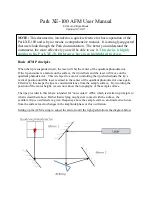
XE-100
Brand: Park Systems Pages: 10

86000
Brand: FINO Pages: 10

8851301
Brand: Bresser Junior Pages: 28

Quanta FEG 250
Brand: FEI Pages: 228

Axioskop
Brand: Zeiss Pages: 32

VFA-12
Brand: LW Scientific Pages: 1

Vision VIS12
Brand: LW Scientific Pages: 1

Student Scope OEM-SF3
Brand: LW Scientific Pages: 1

RV30A
Brand: LW Scientific Pages: 1

Revelation III LED
Brand: LW Scientific Pages: 4


