


1
INSTRUCTION MANUAL
07/2006
PLEASE READ CAREFULLY AND UNDERSTAND BEFORE USING THE
EQUIPMENT
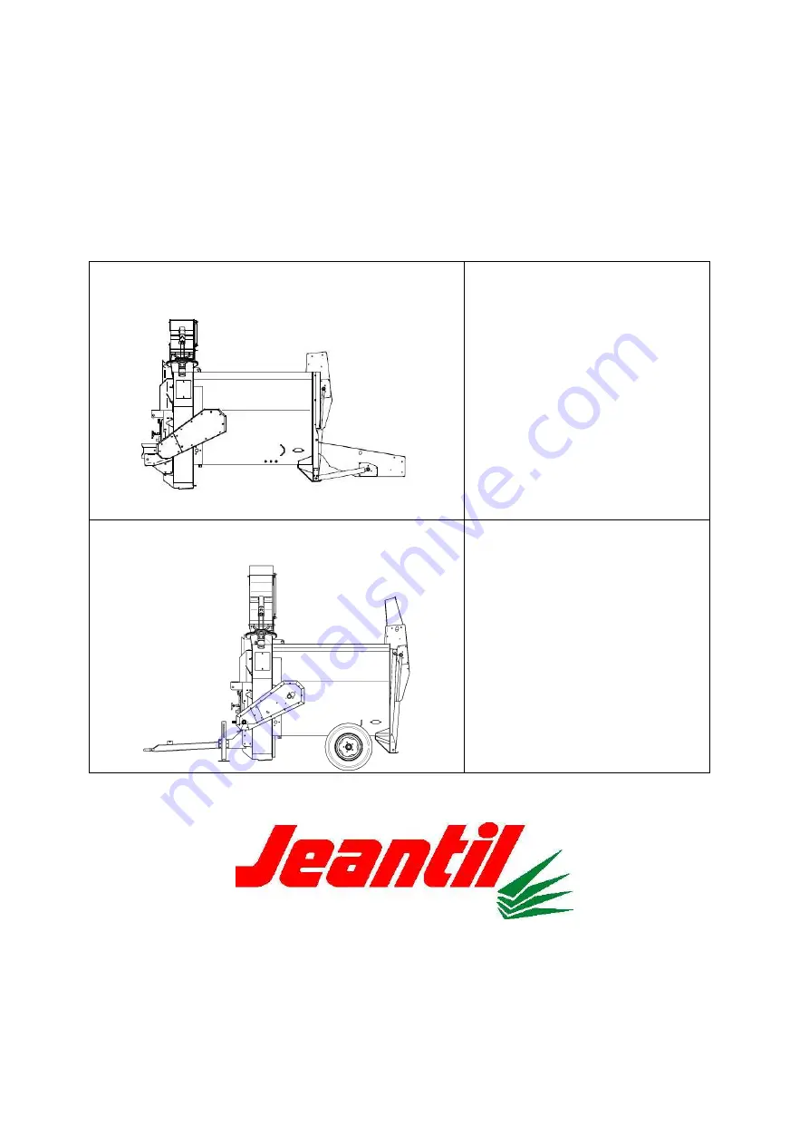
Mounted straw blower
PR 2000 R
PR 2000 R GT
3-Point linkage
Semi-trailer straw blower
PR 2000 R
PR 2000 R GT
Rigid axle
JEANTIL
Rue de la Tertrais
ZI La Hautière BP1
35590 L’HERMITAGE France
Tel: 00 33 (0)2.99.64.04.04
Fax: 00 33 (0)2.99.64.19.56
Spares shop Tel: 00 33 (0)2.99.64.04.02


