


Reviews:
No comments
Related manuals for EBA-40
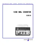
5305 B
Brand: HP Pages: 48

BA364NG
Brand: BEKA Pages: 46

R313FB
Brand: netvox Pages: 13

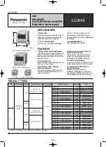
LC2H Series
Brand: Panasonic Pages: 8
LC4H-PS-R4-AC240V
Brand: Panasonic Pages: 11

ARDAC WACS-2
Brand: Money Controls Pages: 77

RBC-5000
Brand: Royal Sovereign Pages: 10

FS-550D
Brand: Royal Sovereign Pages: 8

RBC-ED250
Brand: Royal Sovereign Pages: 12

RBC-ES200
Brand: Royal Sovereign Pages: 12

RBC-ED350
Brand: Royal Sovereign Pages: 12

RBC-EG450-CA
Brand: Royal Sovereign Pages: 13

RBC-4500
Brand: Royal Sovereign Pages: 12

RBC-1002
Brand: Royal Sovereign Pages: 12

RBC-1515-ADBK
Brand: Royal Sovereign Pages: 12

Fast Sort FS-2D
Brand: Royal Sovereign Pages: 12

RBC-Quickcount
Brand: Royal Sovereign Pages: 12

RBC-3200-CA
Brand: Royal Sovereign Pages: 20


