Jay-Lor 51000TM, Owner'S Manual
The Jay-Lor 51000TM Owner's Manual is an essential guide for every user looking to maximize the potential of their product. This comprehensive manual is available for free download, ensuring easy access to vital information on operation, maintenance, and troubleshooting. Visit manualshive.com to grab your copy today.
Share
Download


Reviews:
No comments
Related manuals for 51000TM

grandMA3
Brand: MA lighting Pages: 6

grandMA3
Brand: MA Pages: 3

CONVERGE Matrix
Brand: Clear One Pages: 24

JBL CSM-21
Brand: Harman Pages: 56

MX505WXB
Brand: Tesla Pages: 44

MC32/12
Brand: Yamaha Audio Pages: 18

PRINCIPIO DDI10142
Brand: Moulinex Pages: 49
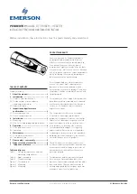
PENBERTHY CTE
Brand: Emerson Pages: 5

HMB 205W
Brand: Hyundai Pages: 32

V-Mixer M-300
Brand: Roland Pages: 8

PMG1000 V2
Brand: SEIKAKU Pages: 11

Easy Mix 6789
Brand: OBH Nordica Pages: 24

PCM Plus Series
Brand: Crate Pro Audio Pages: 12

M-14:2
Brand: D.A.S. Pages: 27

SmartMixer AT-MX341a
Brand: Audio Technica Pages: 12

DOMO DO9026M
Brand: Linea 2000 Pages: 28

7510B
Brand: JBL Pages: 28

C-6200
Brand: Telex Pages: 6


