background image


© Copyright Javad Navigation Systems, Inc.

February, 2007

All contents in this manual are copyrighted by JNS. All rights reserved.

The information contained herein may not be used, accessed, copied, 

stored, displayed, sold, modified, published, or distributed, or otherwise 

reproduced without express written consent from JNS.
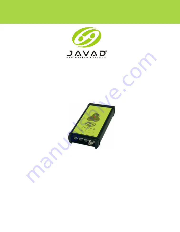
LGG100-GG

Operator’s Manual

Summary of Contents for LGG100-GG

Page 1: ...n this manual are copyrighted by JNS All rights reserved The information contained herein may not be used accessed copied stored displayed sold modified published or distributed or otherwise reproduced without express written consent from JNS LGG100 GG Operator s Manual ...

Page 2: ...www javad com ...

Page 3: ...eling Requirements 12 WEEE Directive 13 Manual Conventions 13 Screen Captures 14 Chapter 1 Introduction 15 Overview 16 Principles of Operation 17 GPS and GLONASS Overview 17 Calculating Positions 17 GNSS Positioning 18 Conclusion 19 Receiver Overview 19 LGG100 GG Accessory Kit 20 Cables 20 Software 20 Literature 21 Getting to Know Your LGG100 GG 21 Internal Components 21 ...

Page 4: ...6 Turning On Off the LGG100 GG 26 Connecting the LGG100 GG and a Computer 27 Establishing an RS232 Cable Connection 27 Establishing a PCView Connection 27 LGG100 GG Configuration 29 MinPad Configuration 33 Collecting Almanacs 39 Chapter 3 Setup and Measuring 41 LGG100 GG Setup 42 DGPS Measuring with the LGG100 GG 45 Setting up a DGPS Base Station 45 Setting up a DGPS Rover 49 Chapter 4 Operation 5...

Page 5: ... OAF 63 Loading OAFs 65 Clearing the NVRAM 66 Using MinPad to Clear NVRAM 67 Using PCView to Clear NVRAM 67 Checking Firmware Version 68 Loading New Firmware 69 Chapter 5 Troubleshooting 71 Things to Check First 72 Receiver Problems 73 Obtaining Technical Support 76 E mail 76 Website 76 Appendix A 77 Creating Scripts 77 Appendix B 79 Specifications 79 General Details 79 GNSS Board Details 83 Conne...

Page 6: ...OF CONT ENTS 2 Power Connector 85 Serial RS 232C Connector 86 GPS GLONASS External Antenna RF Connector 86 Event and 1PPS Timing Connectors Optional 87 Appendix C 89 Safety Warnings 89 General Warnings 89 Usage Warnings 89 Appendix D 91 Warranty Terms 91 ...

Page 7: ...ltipath Reduction 32 LGG100 GG s MinPad 33 Connection Parameters RTS CTS Handshaking 34 Configuration Receiver 34 Receiver Configuration MinPad Tab 35 MarAnt Antenna Offset Measurements 43 Connection Parameters RTS CTS Handshaking 45 Configuration Receiver 46 Receiver Configuration Positioning 46 Base Tab Configuration 47 Base Configuration Ports 48 Port output setup 48 Rover Tab Configuration 50 ...

Page 8: ...nection Parameters RTS CTS Handshaking 63 Tools Receiver Options 64 Option Manager 65 Load OAF 66 Tools Clear NVRAM 67 Help About 68 About PCView 68 Floader Main Screen 69 Set Device Type 70 Program Tab Settings 70 Connection Parameters RTS CTS Handshaking 77 File Manual Mode 78 Power Connector 85 RS 232C Connector 86 ...

Page 9: ...perating the receiver COPYRIGHT All information contained in this Manual is the intellectual property of and copyrighted material of JNS All rights are reserved You may not use access copy store display create derivative works of sell modify publish distribute or allow any third party access to any graphics content information or data in this Manual without JNS express written consent and may only...

Page 10: ...e sup plied by JNS or downloaded from a JNS website the Software in connection with the LGG100 GG constitutes acceptance of these Terms and Conditions in this Manual and an agreement to abide by these Terms and Conditions The user is granted a personal non exclusive non transferable license to use such Soft ware under the terms stated herein and in any case only with a single LGG100 GG or single c...

Page 11: ...e centers Users should review and heed the safety warnings in Safety Warnings on page 89 MISCELLANEOUS The above Terms and Conditions may be amended modified superseded or canceled at any time by JNS The above Terms and Conditions will be governed by and construed in accordance with the laws of the State of California without reference to conflict of laws Regulatory Information The following secti...

Page 12: ... receiving antenna Move the equipment away from the receiver Plug the equipment into an outlet on a circuit different from that to which the receiver is powered Consult the dealer or an experienced radio television technician for additional suggestions Any changes or modifications to the equipment not expressly approved by the party responsible for compliance could void your authority to operate s...

Page 13: ...t your supplier where you purchased the product or con sult Manual Conventions This manual uses the following text conventions Example Description Satellites This format represents titles of dialog windows boxes names of menu options Internal This format identifies program interface objects such as check boxes edit boxes radio buttons etc Ctrl V This format is used to specify keys and key combinat...

Page 14: ...ification that an action will result in system damage loss of data loss of warranty or personal injury DANGER UNDER NO CIRCUMSTANCES SHOULD THIS ACTION BE PERFORMED Screen Captures This manual includes sample screen captures Your actual screen can look slightly different from the sample screen due to the receiver you have con nected operating system used and settings you have specified This is nor...

Page 15: ...of the LGG100 GG including its features and physical elements In addition a brief description of the principals of GPS operation is presented Overview 16 Principles of Operation 17 Receiver Overview 19 LGG100 GG Accessory Kit 20 Getting to Know Your LGG100 GG 21 Option Authorization File OAF 23 ...

Page 16: ...s of the United States and the GLONASS Global Navigation Satellite Systems of the Russian Federation LGG100 GG can track simultaneously up to 25 GPS GLONASS and SBAS sat ellites Operation frequency for GPS SBAS is 1575 4200 MHZ and operation frequency range for GLONASS is 1602 5625 1615 5000 MHz LGG100 GG is a receiver intended for following markets navigation aviation timing oil platform position...

Page 17: ...ASS satellites between 10 and 16 satellites are visible For information on the current status of the GPS constellation visit http tycho usno navy mil or http www navcen uscg gov For GLONASS visit http www glonass ianc rsa ru Despite numerous technical differences in the implementation of these systems both GPS and GLONASS have three essential components Space GPS and GLONASS satellites orbiting ap...

Page 18: ...econds GPS satellites broadcast almanac data cyclically with a period of 12 5 minutes GLONASS satellites broadcast almanac data cyclically with a period of 2 5 minutes GNSS Positioning Achieving quality position results requires the following three elements Accuracy The accuracy of a position depends upon the number signal integrity and placement also known as Dilution of Precision or DOP of satel...

Page 19: ...begin tracking visible GNSS satellites Each of the receiver s channels can be used to track C A L1 and Carrier signals The num ber of channels available allows the receiver to track all visible satellites at any time and location Once the signal is locked in the channel it is demodulated and necessary signal parameters carrier and code phases are measured In addition broadcast navi gation data are...

Page 20: ...n external device hand held controller or computer Receiver to SAE power cable connects the receiver s power port and the power supply s SAE connector or the extension cable s SAE connector SAE to SAE cable extension connects SAE con nectors over longer distances Software Standard LGG100 GG software includes PCView Lite controller software that can run on a Windows based computer Please refer to t...

Page 21: ...to Know Your LGG100 GG The LGG100 GG is 160 mm wide 35 mm deep and 85 mm high weighs 0 316 kg The casing allocates space for JNS100 GG board It is based on our JNScore chip includes an on board power supply that accepts any unregulated voltage from 9 to 35V DC The LGG100 GG has standard interior receiver components and panel for user interface communication and power supply For LGG100 GG specifica...

Page 22: ...ith MinPad Figure 1 2 LGG100 GG Top Panel MinPad The simple user interface for the LGG100 GG receiver The MinPad consists of two keys and two three color LEDs See Using MinPad on page 54 for descriptions and usages of its components Front Panel Figure 1 3 shows the LGG100 GG s front panel components PWR A B ANT Figure 1 3 LGG100 GG Front Panel PWR The power input port to which an external power so...

Page 23: ...G receivers ship with a temporary OAF that allows the receiver to be used for a predetermined period When the receiver is purchased a new OAF activates desired purchased options permanently Receiver options remain intact when clearing the NVRAM or resetting the receiver The OAF enables the following kinds of functions for LGG100 GG For a com plete list of available options and details visit the JN...

Page 24: ...24 LGG100 GG Operator s Manual www javad com Notes ...

Page 25: ...ation 29 MinPad Configuration 33 Collecting Almanacs 39 Chapter Tip Before you can use your LGG100 GG you need to 1 Power your LGG100 GG See Powering the LGG100 GG on page 26 2 Configure the various parts of your LGG100 GG See Connecting the LGG100 GG and a Computer on page 27 LGG100 GG Configuration on page 29 MinPad Configuration on page 33 and 3 Collect an almanac See Collecting Almanacs on pag...

Page 26: ...ce or cleaning of the supply while plugged in Always remove supply from AC power before attempting service or cleaning Warning If the voltage supplied is below the minimum specification the receiver will suspend operation If the voltage supplied is above the maximum specifica tion the receiver may be permanently damaged voiding your warranty Make sure cords are located so that will not be stepped ...

Page 27: ...CView to load OAFs and configuration files to the receiver Establishing an RS232 Cable Connection 1 Using the RS232 cable connect the serial port of your computer usu ally COM1 to the receiver s serial port A 2 Press the power buttons on the LGG100 GG and computer to turn them on 3 Continue with steps described in Establishing a PCView Connection Establishing a PCView Connection PCView is a softwa...

Page 28: ...the following parameters and click Connect Figure 2 2 Set the Connection mode Direct Set the port for your computer typically COM1 COM2 for RS232 connection from the Port drop down list Set the communication rate between the receiver and the computer usually 115200 from the Baud rate drop down list Enable RTS CTS handshaking Figure 2 2 RS 232 Connection Parameters Once a PCView connection with the...

Page 29: ...aved in the receiver s memory and will be reflected when you use the MinPad The full range of PCView configuration and function is outside the scope of this manual Notice Refer to the PCView Software Manual to manage all possible LGG100 GG con figurations The following configuration is recommended for the most common applica tions However you can select configuration parameters as needed for your ...

Page 30: ... Receiver Figure 2 4 Figure 2 4 Configuration Receiver The Receiver Configuration dialog box displays Figure 2 5 Figure 2 5 Receiver Configuration 3 Click the MinPad tab configure the following settings and click Apply Figure 2 6 on page 31 Set the Recording interval in seconds Set the Elevation mask for Log file in degrees Enter the File name prefix ...

Page 31: ...s obstructions buildings trees etc and or the antenna location is near reflective objects configure the receiver to reduce errors from these sources 4 Click the Advanced tab on the Receiver Configuration screen and then click the Multipath Reduction subtab Enable the following boxes and click Apply Figure 2 7 on page 32 Code multipath reduction Carrier multipath reduction ...

Page 32: ...e Receiver Configuration screen 6 Click on File Disconnect and then File Exit to quit PCView Notice Disconnecting the LGG100 GG from the computer before exiting will eliminate any possible conflict in the management of your serial ports Once the LGG100 GG is configured the configuration will remain until you change it either using PCView or clearing the receiver s NVRAM ...

Page 33: ... off Turn data recording on or off FN key Change the LGG100 GG s information mode Show the number of GPS green and GLONASS orange satellites being tracked STAT LED Show data recording status REC LED Show each time data records to internal memory REC LED Show the status of post processing mode static or dynamic when perform ing a Post Processing Kinematic measuring with the help of FN key REC LED U...

Page 34: ...k Configuration Receiver Figure 2 10 Figure 2 10 Configuration Receiver 5 Click the MinPad tab set the following parameters and click Apply Figure 2 11 on page 35 See the following pages for descriptions of these parameters Recording interval on page 35 Elevation mask for log file on page 35 File name prefix on page 35 Always append to the file on page 36 Files Creation mode on page 36 Automatic F...

Page 35: ...ult value is one second Elevation Mask for Log File parameter This parameter specifies the minimum elevation angle for the satellites whose data will be put in the receiver files logged when pressing FN The default value is five degrees File Name Prefix parameter This parameter specifies what prefix will be added to the names of the receiver files created when pressing FN The prefix can be up to 2...

Page 36: ...module Period is equal to Phase More precisely a new log file opens immediately before the scheduled epoch causing data tagged with this epoch to be recorded to the new log file When opening a new log file the receiver enables the default set of messages outputted with the default output period Both the default set of messages and the default output period are programmable Period specifies the tim...

Page 37: ...n the MinPad s normal extended information modes and start stop data recording of Static measuring FN pressed less than 1 second changes the information mode Normal or Extended Information EI Modes FN pressed from 1 to 5 seconds starts or stops recording Static post processing mode Occupation mode switch pressing FN less than one second will insert into the corresponding log file a message indicat...

Page 38: ... this file A new log file will open when power is restored and data will log to this file 3 File specified receiver data logging not started No file will open with this name Data logging will not start when power is restored No file will open with this name Data logging will not start when power is restored A log file with this name will open and data logging will start after power is restored 4 N...

Page 39: ...lmanac you can considerably reduce the time needed to search for and lock on to satellite signals The LGG100 GG regularly updates the almanac and stores the most recent almanac in receiver s Non Volatile Random Access Memory NVRAM 1 Set up the LGG100 GG connect the external antennas if needed in a location with a clear view of the sky 2 Turn on the LGG100 GG Wait for about 15 minutes while the uni...

Page 40: ...40 LGG100 GG Operator s Manual www javad com Notes ...

Page 41: ...www javad com LGG100 GG Operator s Manual 41 SETUP AND MEASURING 3 In this chapter LGG100 GG Setup 42 DGPS Measuring with the LGG100 GG 45 ...

Page 42: ...The LGG100 GG is used with an external antenna Follow the steps below to connect an external antenna to the LGG100 GG and measure its offset 1 Attach the antenna to a tripod or bipod and center it over the point at which data will be collected 2 Measure the antenna height Antennas have two types of measurements Vertical measured from the marker to the antenna reference point ARP located on the bot...

Page 43: ...nna height point name and start time in the field notes 4 Attach the flexible RF cable from the external antenna to the antenna connector on the bottom panel of the LGG100 GG Table 3 1 Antenna Offset Values for Receiver Options Antenna Radius A Vertical Offset C Slant Offset MarAnt SHMM1 69 mm 0 226 ft SHMM2 89 7 mm 0 294 ft 54 3 mm L1 26 8 mm L1 ...

Page 44: ...REC recording LED light turns green This indicates that a file has opened and data collection has started The REC LED blinks each time data is saved to the internal memory Tip You can use PCView to configure data logging See MinPad Configuration on page 33 or refer to the PCView Software Manual for more information 3 When finished press and hold the FN key until the REC LED light goes out 4 Press ...

Page 45: ...GPS Base Station To configure a DGPS Base station using PCView take the following steps 1 Set up the Base station receiver s antenna as described in LGG100 GG Setup on page 42 2 Connect an external modem to port B for the LGG100 GG receiver 3 Turn on the receiver 4 Check the LED for tracked satellites 5 Connect your receiver and computer See Connecting the LGG100 GG and a Computer on page 27 for t...

Page 46: ...f the Receiver Configuration screen 9 Select the Positioning tab and set the Position Masks Elevation mask parameter to 15 Figure 3 4 Figure 3 4 Receiver Configuration Positioning 10 Select the Base tab and set the following parameters Figure 3 5 on page 47 GPS GLO at one time enable Antenna position enter Lat Lon and Alt values Do one of the fol lowing If known type in the values Click Get from r...

Page 47: ... until the specified interval span completes Examine the Base coordinates on the Base tab they should correspond to the coordinates obtained from the average 12 Click Refresh if the coordinates are zeros Notice The reference geodetic coordinates you specify on this tab relate to the antenna L1 phase center Figure 3 5 Base Tab Configuration ...

Page 48: ...SU R IN G DGPS Measuring with the LGG100 GG 3 13 Select the Ports tab and set the following port parameters Figure 3 6 Figure 3 6 Base Configuration Ports Output drop down list select type and format of differential correc tions Figure 3 7 Figure 3 7 Port output setup ...

Page 49: ...the Low High toggle on the rear panel of the modem 17 Use the Channel button to set the frequency channel Check that the modem transmits the corrections the TX LED will blink red each time data transmits For more details on the settings available for configuring the Base station refer to the PCView Software Manual Setting up a DGPS Rover Use the following steps to set up a DGPS Rover station You s...

Page 50: ... Mode Figure 3 8 Figure 3 8 Rover Tab Configuration 7 Select the Ports tab and set the following parameters for Serial B Figure 3 9 on page 51 Input drop down list select desired differential correction format Period sec leave as is Baud rate drop down list select a baud rate i e the receiver port baud rate at which differential messages will be received from modem ...

Page 51: ...onfiguration Ports 8 Click Apply 9 Click OK to close the Receiver Configuration screen 10 On the main screen check the LQ field to ensure the receiver obtains differential corrections Usually the receiver will start to output the coordinates of the antenna s phase center along with the solution type within 10 30 seconds ...

Page 52: ...52 LGG100 GG Operator s Manual www javad com Notes ...

Page 53: ...G Operator s Manual 53 OPERATION 4 In this chapter Using MinPad 54 Downloading Files to a Computer 59 Deleting Files 62 Managing Receiver Options 63 Clearing the NVRAM 66 Checking Firmware Version 68 Loading New Firmware 69 ...

Page 54: ...e tracked the STAT LED will produce one blink for each tracked satellite green for GPS orange for GLONASS FN Key and Record LED Table 4 1 on page 55 summarizes FN key functions and REC LED statuses See FN Key Mode parameter on page 37 for information on setting FN key modes Pressing the FN key for less than one second switches the receiver between different information modes normal and extended in...

Page 55: ... Pressing the FN key for more than five and less than eight seconds will turn the baud rate of serial port A to 9600 After about five seconds of pressing the FN key the REC LED becomes red Release the FN key while the REC LED is red during the next three seconds Pressing the FN key for more than eight seconds has no impact After loading new firmware or clearing the receiver s NVRAM the receiver ch...

Page 56: ...5 sec onds If FN key mode is LED blink mode switch Green Release to start data recording post pro cessing occupation mode undefined If FN key mode is Occupation mode switch Green Release to start recording Kinematic or Static post processing occupation mode Pressed for 5 8 sec onds Red Release to turn serial port A baud rate to 9600 bps Pressed for 8 sec onds No light No function Table 4 1 FN key ...

Page 57: ... mode undefined If FN key mode is Occupation mode switch Green Data recording started Kinematic post processing occupation mode Orange Data recording started Static post pro cessing occupation mode Pressed for 1 second If FN key mode is LED blink mode switch Orange Release to change information mode If FN key mode is Occupation mode switch Orange Release to toggle between Static and Kinematic post...

Page 58: ...ther cases Sufficient data for position computation GPS S N ratios are good Table 4 2 GLONASS S N ratios are good Table 4 2 Oscillator s frequency offset is less than three ppm Oscillator s Allan Variance is better than 2 7e 10 Continuous tracking time is more than 15 minutes Table 4 2 CA L1 P L1 GPS 51 39 GLONASS 51 49 In EIM the STAT LED blinks seven times per cycle Each blink could be orange re...

Page 59: ... amount of files and information so downloading the files to a computer ensures that no files are lost You should download files as soon as possible after collecting data at the job site PCView provides a File Manager to download files to your computer and delete files from the LGG100 GG 1 Connect your receiver and computer See Connecting the LGG100 GG and a Computer on page 27 for this procedure ...

Page 60: ...oad path tab on the File Manager dialog box Figure 4 4 Figure 4 4 Find Files to Download 6 Navigate to and open the folder in which to download and store files Or type a new folder name and click Create to create a new folder in which to download and store files Open this new folder 7 Select the Download files tab 8 Select the file s you want to download Figure 4 5 on page 61 ...

Page 61: ...veral files at once or hold down the Ctrl key and click on individual files Figure 4 5 Download Files 9 Click the Download button During the download status indicators display next to each file Figure 4 6 Blue indicator file in queue for downloading Red indicator file currently downloading Green indicator file has successfully downloaded Figure 4 6 Download Files Status Indicators ...

Page 62: ... page 27 for this procedure 2 Start PCView 3 On the Connection Parameters dialog box enable RTS CTS handshaking See Figure 4 2 on page 59 4 Click File File Manager See Figure 4 3 on page 60 5 On the Download files tab select the file s you want to delete Figure 4 7 on page 62 To select multiple files hold down the shift key and click on nonsequential files to select several files at once or hold d...

Page 63: ...details visit the JNS website You can check the status of your receiver s options and load any new OAFs using the RS232 cable a computer and PCView Refer to the PCView Software Manual for a more complete description of the PCView software 1 Connect your receiver and computer See Connecting the LGG100 GG and a Computer on page 27 for this procedure 2 Start PCView 3 On the Connection Parameters dial...

Page 64: ...Current the current status of the option Purchased if the option is purchased or not Leased if the option is leased or not Expiration date the date the option will be disabled if applicable Since Options can be both purchased and leased the Current status of the option displays the currently effective value Option values can be 1 or the firmware version does not support this option 0 the receiver ...

Page 65: ...flicts with serial port manage ment Loading OAFs Javad Navigation Systems dealers provide customers with OAF files For any OAF related questions E mail JNS at options javad com Please have your receiver ID number available see Checking Firmware Version on page 68 1 To load a new OAF follow steps one and two in Checking an OAF on page 63 2 Click Load at the bottom of the Option Manager screen see F...

Page 66: ...ing such as almanac and ephemeris data and receiver position The NVRAM also keeps the current receiver s settings such as active antenna input elevation masks and recording interval and information about the receiver s internal file system Even though clearing the NVRAM is not a common nor normally a recom mended operation there are times when clearing the NVRAM can eliminate communication or trac...

Page 67: ...it until the STAT and REC LEDs are green 5 Wait until the STAT and REC LEDs blink orange Release the FN key while the STAT and REC LEDs blink orange Using PCView to Clear NVRAM 1 Connect your receiver and computer See Connecting the LGG100 GG and a Computer on page 27 for this procedure 2 Start PCView 3 Click Tools Clear NVRAM Figure 4 12 4 Click OK at the clear NVRAM confirmation dialog box Figur...

Page 68: ... Computer on page 27 for this procedure 2 Start PCView 3 Click on Help About Figure 4 13 Figure 4 13 Help About The About PCView dialog box opens Figure 4 14 Figure 4 14 About PCView About PCView lists important information about the different hardware accessories and software properties This list includes the following which you will need if you contact JNS or your dealer Receiver model Receiver ...

Page 69: ...load two files when loading new firmware These files must come from the same firmware package The LGG100 GG uses FLoader a Windows based utility to load firmware into the receiver You can download FLoader to your computer from the JNS website http www javad com For more information refer to the FLoader User s Manual also available on the JNS website 1 Download and install FLoader if applicable 2 D...

Page 70: ...od to Soft Break Capture recommended Figure 4 17 Figure 4 17 Program Tab Settings 9 Browse for and select the receiver board s RAM file and Flash file 10 Click Load and wait until 100 of the files load into your receiver Notice If you selected an incorrect RAM or Flash file an error message displays at the bottom of the dialog box Reselect the correct file 11 Click File Exit 12 Clear the receiver ...

Page 71: ...intenance and safety instructions pro vided in this manual you should have few problems with your LGG100 GG This chapter will help you diagnose and solve some common minor problems you may encounter with your LGG100 GG receiver Things to Check First 72 Receiver Problems 73 Obtaining Technical Support 76 ...

Page 72: ...eck the cables Cables became defective more often than the devices do Check the sections below for available solutions Reset the receiver using PCView Tools Reset receiver Restore factory default settings using PCView click Configuration Receiver then Set all parameters to defaults Clear the NVRAM see Clearing the NVRAM on page 66 Initialize the file system click Tools Initialize file system this ...

Page 73: ...cable The receiver port used for connection is not in Command mode Connect your receiver and a computer using a free port see Connecting the LGG100 GG and a Computer on page 27 and start PCView Click Configuration Receiver Ports Change the Input for the serial port used for connection to Command Problem The receiver does not lock on to satellites for a long period of time Causes Solutions The rece...

Page 74: ...erential solutions Causes Solutions Incorrect Base coordinates entered Specify the correct coordinates for the Base station using PCView or other suitable field data collection software The receiver is not configured as a Base or Rover If the receiver should function as a Base ensure it has the proper configuration See DGPS Measuring with the LGG100 GG on page 45 for further information If the rec...

Page 75: ...o the same radio channel A discrepancy exists between the differential standards used at the Base and Rover receiv ers Ensure the Base and Rover receivers use the same corrections input output format Connect your receiver and a computer and start PCView See Connecting the LGG100 GG and a Computer on page 27 Click Configuration Receiver Ports and set the same input output format for both receivers ...

Page 76: ...ns Related To Use Hardware receivers antennas firmware hardware javad com OAF options javad com Ensemble ensemble javad com PCView pcview javad com FieldView fieldview javad com If in doubt which e mail address to use for your particular question please send it to support javad com Website The Javad Navigation Systems website provides current information about JNS s line of products The support ar...

Page 77: ...e the fol lowing procedure to create script files Tip For more information on script files see the PCView Software Manual 1 Connect your receiver and computer See Connecting the LGG100 GG and a Computer on page 27 for this procedure 2 Once connected start PCView On the Connection Parameters dialog box enable RTS CTS handshaking Figure A 1 and then click Connect Figure A 1 Connection Parameters RTS...

Page 78: ... Send command after each one See table below for these commands To Create Daisy Chain To End Daisy Chain set dev ser b rate 38400 set dev ser b echo cur term set dev ser b imode echo set cur term eoff QUIT set cur term echo dev null set cur term imode echo set cur term echo dev ser c QUIT set cur term imode cmd set dev ser b echo dev null set dev ser b imode cmd set dev ser b rate 38400 set cur te...

Page 79: ...eral Details Table B 1 lists receiver component details Table B 1 LGG100 GG General Specifications Physical Enclosure Aluminum extrusion waterproof Color JNS Green and black Dimensions H 160 x W 85 x D 35 mm Weight 0 316 kg Keys Power On Off Function FN start stop data logging switch information mode LEDs STAT satellite and receiver status REC record and data status ...

Page 80: ...to 460 8 Kbps CAN 2 0 A B port up to 1 Mbps Event marker One Event marker input 1 PPS timing 1 PPS timing output LVTTL synchronized to GPS UTC or GLONASS IRIG Serial Time Code Output Supported Formats A130 A132 A133 B120 B122 B123 Antenna External GPS GLONASS Antenna LNA Power GNSS Antenna GPS GLONASS Antenna External Wireless communication Communication External only Data Features Up to 100 Hz up...

Page 81: ... type 1 3 9 31 32 34 Process interval 1Hz standard 5 10 20 50 100 Hz optional Output interval for RTCM correction data 1Hz standard 5 10 20 50 100 Hz optional RTK Correction format CMR2 CMR Trimble compatible RTCM SC104 Ver 2 2 2 3 RTCM 2 x message type 3 18 19 20 21 22 23 Ambiguity initialize OTF Baseline Length Up to 20 km Initialize time 15 seconds to 10 min depending on the base line length an...

Page 82: ...ng level Selectable thresholds Low 95 Medium 99 5 High 99 9 Data Output Real time data outputs RTCM 104 version 2 2 2 3 CMR CMR ASCII Output NMEA 0183 version 3 0 Other Outputs JNS format Output Rate Up to 100 times per second 100Hz Measuring Modes Measuring Modes Static Kinematic Stop and Go RTK Real time Kinematic DGPS Differential GPS SBAS DGPS Measuring Accuracy Static 5mm 1 5ppm x D for Singl...

Page 83: ...s L1 C A Full Cycle Carrier GLONASS Tracking Functions Multi path reduction Code Smoothing interval Code and Carrier WAAS EGNOS Standard Data Output Real time data outputs RTCM SC104 version 2 2 2 3 CMR CMR ASCII Output NMEA 0183 version 3 0 Other Outputs JNS format Output Rate Up to 100 times per second 100Hz Memory Internal Memory Up to 128 MB of on board non removable memory for data storage Da...

Page 84: ...erence time GPS GLONASS UTC USNO UTC SU Resolution 5 ns Accuracy1 2 ns Timing Output optional Number of Timing ports 1 2 0 V min at 50 Ohm load Connector type BNC Edge Rise Fall Period 10 to 1000000000 ms Offset 500000000 to 500000000 ms 500000 to 500000 ns Reference time GPS GLONASS UTC USNO UTC SU Resolution 5 ns Accuracy1 2 ns Event Marker optional Number of Event Marker ports 1 Connector type ...

Page 85: ...GND Ground power return 5 Not used Reference time GPS GLONASS UTC USNO UTC SU Resolution 5 ns 1 Due to a hardware limitation PPS Timing signals are discrete with a resolution of 20 ns LGG100 GG receiver however allows you to compensate for this discreteness error You can force the receiver to generate for each PPS Timing pulse a message containing the offset between the scheduled PPS Timing pulse ...

Page 86: ...al Name Dir Details 1 Power Output O External Power Output I 0 2A in all ports 2 GND I O Signal ground 3 CTS I Clear to send 4 RTS O Request to send 5 RXD I Receive data 6 TXD O Transmit data 7 Not used GPS GLONASS External Antenna RF Connector The external antenna connector type Table B 5 is a TNC RF connector with an Applied Engineering Product part number 6001 7051 003 Table B 5 External Antenn...

Page 87: ...or s Manual 87 APPENDIX Specifications Event and 1PPS Timing Connectors Optional The Event and 1PPS Timing connectors are coaxial female receptacles of BNC series Kings Electronics part number KC 79 108 These connectors are optional ...

Page 88: ...88 LGG100 GG Operator s Manual www javad com Notes ...

Page 89: ...altering the product With unauthorized accessories Without proper safeguards at the measuring site Contrary to applicable laws rules and regulations DANGER THE LGG100 GG SHOULD NEVER BE USED IN DANGEROUS ENVIRONMENTS USE IN RAIN OR SNOW FOR A LIMITED PERIOD IS PERMITTED Usage Warnings CAUTION If this product has been dropped altered transported or shipped without proper packaging or otherwise trea...

Page 90: ...erator s Manual www javad com APPENDIX Safety Warnings C Inform JNS immediately if this product does not function prop erly CAUTION Only allow authorized JNS warranty service centers to service or repair this product ...

Page 91: ... service to repair damage to the product resulting from an accident disaster misuses abuse or modification of the product Warranty service may be obtained from an authorized JNS warranty service dealer If this product is delivered by mail purchaser agrees to insure the prod uct or assume the risk of loss or damage in transit to prepay shipping charges to the warranty service location and to use th...

Page 92: ...chnology Drive San Jose CA 95110 USA Phone 1 408 573 8100 Fax 1 408 573 9100 www javad com LGG100 GG Operator s Manual Rev 1 1 2 07 2007 Javad Navigation Systems All rights reserved No unauthorized duplication ...

Reviews: