Janome DC4030P, Service Manual
The Janome DC4030P is a versatile and reliable sewing machine perfect for beginner and experienced sewers alike. For those in need of a Service Manual or user manual, you can easily download it for free from manualshive.com. This comprehensive manual will guide you through all the machine's features and functions.
Share
Download


Reviews:
No comments
Related manuals for DC4030P

Memory Craft 9450QCP
Brand: Janome Pages: 124

170 / 180
Brand: Ricoh Pages: 147

NHL 15
Brand: Numatic Pages: 52

EASY TURF TD-01
Brand: We R memory keepers Pages: 20

4313385
Brand: NexxTech Pages: 5
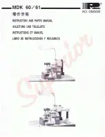
MDK 60 Series
Brand: Racing Pages: 3

HCG Series
Brand: Happy Pages: 98

PF-55
Brand: Neopost Pages: 11

950700
Brand: Lafferty Pages: 16

950 RX
Brand: HTC Pages: 56

MSB-11 ORB
Brand: Pacific Floorcare Pages: 24

AMS-221EN-HS3020/7200
Brand: JUKI Pages: 70

BB 700
Brand: Husqvarna Pages: 80

KM-2510A
Brand: SunStar Pages: 76

Advance 9087381020
Brand: Nilfisk-Advance Pages: 68

50000593
Brand: Nilfisk-Advance Pages: 107

56108110 SC8000 48 LPG
Brand: Nilfisk-Advance Pages: 225

56393900
Brand: Nilfisk-Advance Pages: 28


