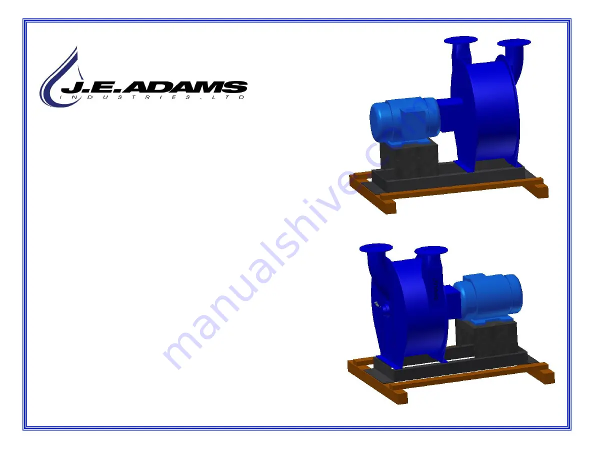
background image

Models-

M24B & M30B Vacuum Producer

Page 2

Product Information

Page 3

Safety Instructions

Page 4 - 5

Receiving, Handling & Storage

Page 5 - 8 

Installation Steps

Page 8 - 9

Pre-Startup Checks/First Startup

Page 10

Operating Temperatures

Page 11 - 13

Coupler Alignment

Page 14 - 17

Lubrication/ Bearing Replacement

Page 18

19

Setting Butterfly Intake Valve

Page 20 - 24

Surge and Motor Control Options

Page 25 - 34

Optional VFD and Transducer Set-up

REV 06/23/23

1

Summary of Contents for M24B

Page 1: ...ge Page 5 8 Installation Steps Page 8 9 Pre Startup Checks First Startup Page 10 Operating Temperatures Page 11 13 Coupler Alignment Page 14 17 Lubrication Bearing Replacement Page 18 19 Setting Butterfly Intake Valve Page 20 24 Surge and Motor Control Options Page 25 34 Optional VFD and Transducer Set up REV 06 23 23 1 ...

Page 2: ...can Key number can be found on the tag that comes attached to the keys There may be more than one key number depending on unit Please keep this information with your records MODEL ____________________________ ORDER ____________________________ SERIAL ____________________________ DATE PURCHASED ___________________ MOTOR F L A_______________ MOTOR NO LOAD AMPS____________ J E Adams Industries 1025 6...

Page 3: ...g that is burning or smoking such as cigarettes matches or hot ashes Do not use without dust bag and or filters in place SAVE THESE INSTRUCTIONS Installation Instructions Determine location to mount unit DANGER THIS EQUIPMENT INCORPORATES PARTS SUCH AS SWITCHES MOTORS OR THE LIKE THAT TEND TO PRODUCE ARCS OR SPARKS THAT CAN CAUSE AN EXPLOSION WHEN LOCATED IN GASOLINE DISPENSING AND SERVICE STATION...

Page 4: ... the time to review this manual in its entirety to assure that you are familiar with all the requirements and features of your equipment Proper installation operation and maintenance will assure the user of years of trouble free service Always refer to your specific model number and serial number which are stamped on the nameplate attached to the inlet head Our ongoing commitment to your satisfact...

Page 5: ...r locations are preferable The location selected should be clean dry properly drained and adequately ventilated Plan ahead Ample room is required for maintenance lubrication and the removal of the machine or driver for servicing FOUNDATION The blower exhauster should be located on a solid level and flat surface The best surface is a reinforced concrete slab however a well reinforced above grade su...

Page 6: ...ed to inlet of producer Inlet pipe from vacuum stations Main Collector Producers are generally installed inside buildings if so best to route exhaust outside Vacuum Producer Turbine REV 06 23 23 Make sure the weight from piping is well supported and not putting strain on the exhaust outlet 6 ...

Page 7: ...otors and starters to avoid tripping breakers or blowing fuses unnecessarily when the blower exhauster is energized JE Adams recommends following NEC article 430 when installing electric motors Electrical Soft Starters Electrical soft starters are used reduce the voltage supplied to the motor when it is energized which reduces the inrush current The voltage is then slowly increased to the line vol...

Page 8: ...d in the intake or discharge piping 4 Remove coupling guard and recheck coupling alignment The blower exhauster and motor shafts were properly aligned at the factory prior to shipment However rough handling in transit could have disturbed this alignment Therefore alignment MUST be rechecked and the unit realigned if necessary Refer to coupling alignment instructions in the COUPLING ALIGNMENT secti...

Page 9: ...strict the air flow Note It will take about 20 seconds for the unit to come up to full speed with the air flow restricted 9 Place an amp meter on one incoming power lead to measure the amp draw Note A true RMS meter is best to measure 3 phase current 10 If your blower exhauster is equipped with a butterfly intake valve follow the procedure outlined in the SETTING THE BUTTERFLY INTAKE VALVE section...

Page 10: ...measured on the bearing housing Standard alarm circuitry if supplied is set to alarm at 230 F 110 C If bearing temperature monitors are not supplied check bearing housing temperatures periodically and notify JE Adams if readings exceed 220 F 104 C DISCHARGE AIR TEMPERATURE Under normal operating conditions using ambient or atmospheric air typical discharge air temperatures may also exceed 200 F 93...

Page 11: ...warranty Misalignment is one of the most common causes of unit vibration and will cause premature bearing failure FINAL SHAFT ALIGNMENT IS THE RESPONSIBILITY OF THE INSTALLER OWNER The following conditions can affect alignment and can be a factor in trying to achieve a good alignment 1 Base and foundation not level and smooth 2 System piping not isolated with flexible sleeve or expansion joint 3 B...

Page 12: ... straight edge across the outside diameters O D of the coupling hubs at 90 degree intervals to check and correct the parallel misalignment Use the calipers to check and correct the angular misalignment The calipers should be used at the same 90 degree intervals as the straight edge LASER ALIGNMENT METHOD The laser alignment method uses a laser to span the shaft to shaft distance As both shafts are...

Page 13: ...ce dial indicators are used The rim reading measures the offset between the coupling halves The face reading measures the angular difference between the faces of the coupling The procedure is as follows 1 Clamp dial indicator on driving Motor side of coupling and locate the indicator probe on the rim O D of the driven Blower coupling half Rotate shaft and take reading at 90 degree intervals to det...

Page 14: ...LATION OF THESE Qty 2 MUST BE DONE BEFORE START UP OF EQUIPMENT INSTALLATION When you receive your JE Adams centrifugal vacuum producer it will be necessary to install both of the automatic lubricators to provide the proper amount of lubrication to the bearings The process is as follows 1 Remove to cap on the electronic lubricator that protects the NPT thread 2 The bearing has been plugged to prev...

Page 15: ...or all series blowers and exhausters equipped with 4 bolt flange bearing The manufacturer of these bearings has stated a small amount of grease at frequent intervals is preferable to a large amount at infrequent intervals This is the preferred method of lubrication however automatic lubricators have to be replaced every 9 12 months depending on use If lubricating manually is preferred we do not re...

Page 16: ...R TYPE LITHIUM COMPLEX OIL SYNTHETIC OIL VISCOSITY 445 cSt 40 C VISCOSITY INDEX 150 DROPPING POINT ASTM D2265 509 F 265 C CORROSION PROTECTION PASS TEMPERATURE RANGE 40 F 40 C TO 302 F 150 C TEXTURE SMOOTH COLOR RED Model Interval Grease Amount M24B Weekly 3 5 CC Model Interval Grease Amount M30B Weekly 4 0 CC 16 ...

Page 17: ...ing the bearing to the head With the hardware removed pull the bearing off shaft 4 Install new bearing on the shaft and replace the 4 nuts that hold the bearing to the head and tighten them down to the required torque 5 Remove the set screws from the inner race of the bearing and apply a small amount of medium strength thread locker Reinstall the set screws in the inner race and tighten them down ...

Page 18: ...inlet tube 4 Record the no load amps on the cover of this manual If the system is tight the exhauster will be in surge and should not be ran in this condition for more than 2 minutes 5 Shut the exhauster down REV 06 23 23 SETTING THE BUTTERFLY INTAKE VALVE ON A VACUUM SYSTEM Purpose To establish the maximum volume of air the exhauster can handle within the constraints of the motor 1 With the vacuu...

Page 19: ... the exhauster is at its maximum flow Once either condition a or b is met in step 5 tighten the set screw on the collar at the base of the valve to lock it in place Note This procedure may require periodic adjustment if small leaks develop and certainly if more hose drops are added NEVER EXCEED THE MOTOR F L A IF ANY DETECTION OF NOISE OR VIBRATION SHUT UNIT DOWN IMMEADIATLY IF UNIT IS RUNNING IN ...

Page 20: ...rous to permit volume load requirements to drop so low as to cause surge Perhaps the foregoing will be more easily understood by reference to the sketch below which is a typical pressure volume curve of a centrifugal blower Point A indicates the normal operating point of a blower Point E is the high point on the curve Stable conditions will always be experienced when the volume demand is to the ri...

Page 21: ...dams recommends electronic surge control In the rare occasion that electronic surge control is not appropriate for the job site JE Adams recommends mechanical relief valves The mechanical relief valves are a lower cost option but do require functional checks once or twice a month Mechanical relief valves are much louder than the electronic surge panels so on larger producers can be an issue if the...

Page 22: ...essure relief valve and for best results it should be placed at end of main suction line behind last hose drop This can help keep your overhead pipe flushed of debris by placing it at end of run Pressure Relief Valve Surge Protector REV 06 23 23 Two Pressure Relief Valves example 22 ...

Page 23: ...nits total CFM and vacuum level can vary depending on HP of motor impeller size elevation and temperature REV 06 23 23 Remove outer cover and middle section to access adjustment bolt Hold nut with socket Use 11 16 wrench Tighten will compress spring and not allow as much air in Loosen allows more air in Example for an M30B producer based on the above information PRV should not be sucking air if 4 ...

Page 24: ...t be installed and configured by a licensed electrician and or certified field technician Failure to follow this requirement can result in severe personal injury or even death and or damage to product At minimum bypassing this requirement will void product warranty Motor Starter Smart Motor Control Variable Frequency Drive VFD REV 06 23 23 24 ...

Page 25: ...s Page 26 Setting the dips in the VFD to work with the transducer Page 27 29 Adding a hand off auto switch to VFD Page 30 Setting parameters for VFD Page 31 VFD control navigation Page 32 Transducer set up parameters Page 33 Wiring transducer to VFD control Page 34 Pictorial example of vacuum producer w transducer REV 06 23 23 25 ...

Page 26: ...Remove VFD cover to access DIPS AI1 and AI2 need to be set to 20ma when using transducer REV 06 23 23 26 ...

Page 27: ...REV 06 23 23 27 ...

Page 28: ...Actual wiring of switch to VFD Blue to 11 Red to 2 Yellow to 6 Make sure jumpers are from 1 to 3 and 1 to 11 REV 06 23 23 YELLOW RED 28 ...

Page 29: ...REV 06 23 23 Actual wiring of hand off auto switch box TOP TOP TOP 29 ...

Page 30: ...l take to get motor up to speed Some advanced parameters may override Flying Start En A167 M Enabled Disabled Allows start when still turning from a shut down Automatically adjusts energy needed for a flying start Motor NP Poles A199 M 2 4 2 pole motor 3500RPM 4 pole 1750RPM Motor NP FLA A200 M Name plate n a Enter amps on motor nameplate Auto Mode P042 O 3 Auto Manual Hnd Off Auto On situations w...

Page 31: ...p in programming menu and or select a digit when viewing parameter menu UP or Down arrows Scroll through groups and parameters and or increase decrease the value of a flashing digit ENTER Advance one step in programming menu and or save a change to a parameter value See VFD manual for additional information REV 06 23 23 31 ...

Page 32: ...hange from bar to PSI and then change ASP and AEP values as listed below however transducer is pre programmed at factory to these values 7 30 0 00 ATTENTION Transducer values are preset at the factory so the above values are for reference only REV 06 23 23 32 ...

Page 33: ...SE NOTE THIS IS A TYPICAL ONLY MAY VARY Please refer to inside panel of VFD wiring block schematic and transducer owners manual Brown 11 White 13 Blue 14 w jumper to 9 Black not used Note All other wires removed for better view REV 06 23 23 33 ...

Page 34: ...Transducer and magnehelic gauge go on intake side of vacuum producer Exhaust Intake REV 06 23 23 Plugs To flange on central vac Open to atmosphere 34 ...

Reviews: