background image

1

6XSHU%XV

Š

=,QSXW0RGXOH

ITI Part No. 60-774

˜ÃÌ>>̈œ˜Ê˜ÃÌÀÕV̈œ˜Ã

Document Number: 466-1606 Rev. B
November 2000

Product Summary

Each SuperBus

®

 2000 8-Zone Input Module adds eight 

supervised hardwire zones. Each module includes mounting 
hardware and eight 2.0K ohm end-of-line (EOL) resistors. 
Power for the module is provided by the panel.

Both normally open and normally closed detectors can be 
wired to module inputs. Using an EOL resistor on each loop 
input, the module monitors all zones and alerts the panel if 
there is an open/short circuit.

Advent

® 

panels can support multiple modules for up to 250 

zone inputs. UltraGard

®

 panels can support up to eight 

modules for 64 additional zone inputs. Concord

 panels can 

be expanded up to 76 zone inputs.

For additional security, the plastic case includes space for 
installing a magnet and reed switch that can provide tamper 
protection to detect cover removal.

SuperBus 2000 

vs. 

SuperBus

SuperBus 2000 panels have the ability to auto-address mod-
ule unit numbers. When the panel is powered up, the panel 
automatically reads the unique SuperBus 2000 device ID 
number and assigns a unit number to the module. This elim-
inates manually setting DIP switches and the chance of 
identical unit number conflicts.

SuperBus 2000 Panels
R Advent
R Concord (software versions 2.0 and later)
SuperBus panels communicate with SuperBus 2000 mod-
ules but require the module unit number to first be set man-
ually with DIP switches.

SuperBus Panels
R UltraGard
R Concord (software versions 1.0–1.6)
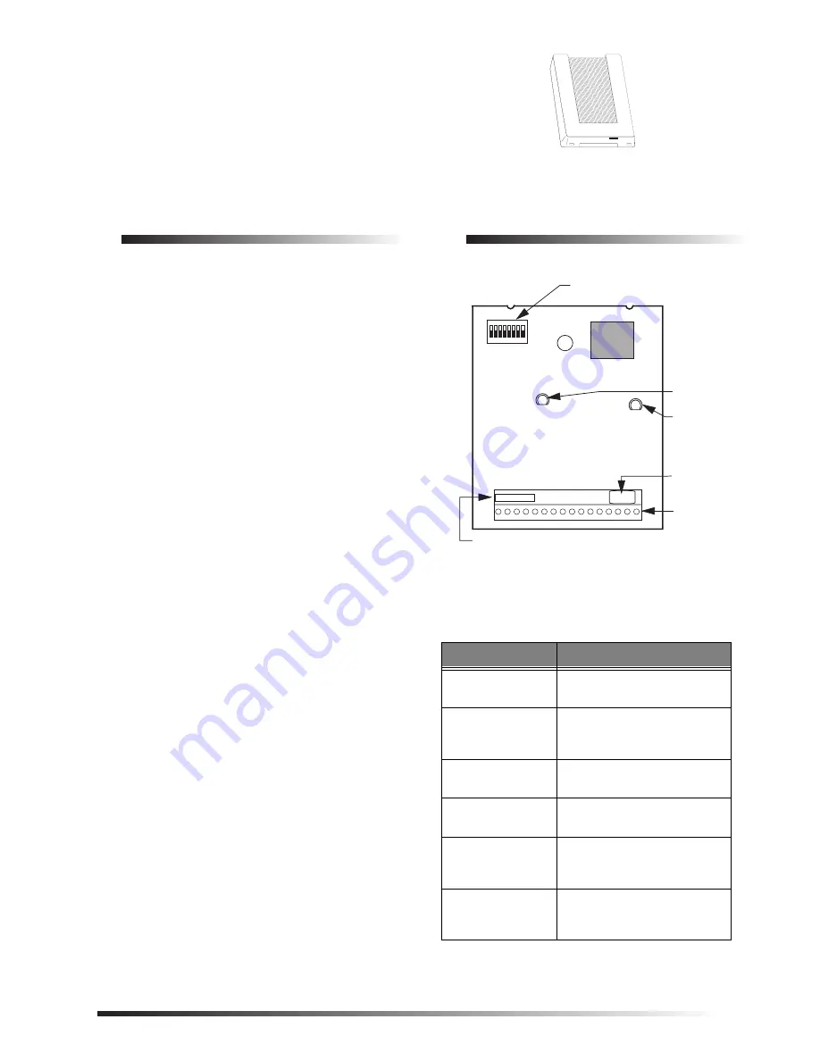
Module Components

Figure 1.

Module Circuit Board Components

Table 1. Module Component Descriptions

Component

Function

Unit Number DIP 
Switches

Used for manually setting unit 
numbers (SuperBus panels).

SuperBus 2000 
Device ID Number 
Label

Identifies unique device ID 
number (SuperBus 2000 
panels).

Software Version 
Label

Identifies the installed 
software version.

Green POWER 
LED

Indicates module power status.

Red BUS LED

Flashes to indicate normal 
communication to the panel 
bus.

Wiring Terminals

Used for power, bus, and 
hardwire zone input 
connections.

SOFTWARE
VERSION LABEL

GREEN POWER 
LED

UNIT NUMBER
DIP SWITCHES

WIRING 
TERMINALS

9712G01A.DSF

RED BUS 
STATUS LED

SUPERBUS 2000 
DEVICE ID
NUMBER LABEL

8557109A.DS4

Summary of Contents for 60-774 - Security SuperBus 2000 8-Zone Input Module

Page 1: ...l is powered up the panel automatically reads the unique SuperBus 2000 device ID number and assigns a unit number to the module This elim inates manually setting DIP switches and the chance of identical unit number conflicts SuperBus 2000 Panels R Advent R Concord software versions 2 0 and later SuperBus panels communicate with SuperBus 2000 mod ules but require the module unit number to first be ...

Page 2: ...r cover tamper R 1 4 inch 6 32 self tapping screws not included for Advent cabinet mounting R Support standoff included with Concord cabinet Installation The module can be mounted R On a wall R Inside an Advent cabinet R Inside a Concord cabinet R Inside a SuperBus module cabinet 60 698 Refer to the cabinet Installation Instructions for installation procedures Ìi For UltraGard installations the mo...

Page 3: ... the module back plate onto the two clips located on the top left corner or center of the cabinet Figure 6 Ìi The two mounting clips in the top right corner of the cabinet are designated for a receiver module but if a receiver module is not being used the mounting clips may be used for the 8 Zone Input Module 5 Push the lower right corner of the module onto the sup port standoff see detail in Figu...

Page 4: ...e installations 1 Figure 8 shows an example of how to connect up to eight normally closed N C or normally open N O intrusion circuits to the module Figure 8 Connecting N C and N O Intrusion Circuits to the Module Table 4 SuperBus Module Panel Wiring Module Terminals Advent Ultra Gard Concord 13 12VDC Red 12 4 14 BUS A Green 13 5 15 BUS B White 14 6 16 GND Black 15 3 9712G03A DSF 1 2 3 4 5 6 7 8 9 ...

Page 5: ... Concord software versions 1 0 1 6 and UltraGard Panels Locate the DIP switches on the module circuit board Fig ure 1 and set switch 1 to M on for manual Figure 10 Set the remaining switches for the desired unit number 1 Do not change DIP switch settings once the panel is powered up UNIT NUMBER 0 7 for UltraGard UNIT NUMBER 0 15 for Concord Figure 10 Module Unit Number DIP Switch Settings Non Supe...

Page 6: ...add SuperBus devices All installed devices are automatically added learned into panel memory when Devices Added is indicated 7 Press twice to return to the Main Menu 8 Both the green and red LEDs turn on for one second The green POWER LED will remain on and the red BUS LED should flash to indicate successful commu nication with the panel Ìi If the green POWER LED is not on or the red BUS LED does ...

Page 7: ...Mutual applied for MEA New York City Material Equipment Acceptance applied for DOD Sensitive Compartment Information Fac applied for ULC Canada Commercial Fire Burglary Warning applied for Ìi See specific panel Installation Instructions for complete UL installation requirements for the system you are installing Table 6 Troubleshooting Problem Action Solution The green POWER LED stays off 1 Check f...

Page 8: ...f the FCC Rules These limits are designed to provide reasonable protection against interference in a residential installation This equipment generates uses and can radiate radio frequency energy and if not installed and used in accordance with the instructions may cause harmful interfer ence to radio communications However there is no guarantee that interference will not occur in a particular inst...

Reviews: