


IPU 40234 Issue 3
Page
1
of
28
IR16 Series
Dual View Thermal Imaging Cameras
User Manual
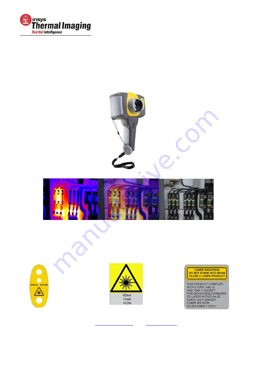
Safety Warning:
The equipment described in this document uses a Class 2 laser. Under no account should
anyone look directly into the laser beam or the laser beam exit aperture, irreversible damage
to the eye may occur. The laser should not be operated when there are personnel in the
imager’s field of view.
Caution – use of controls or adjustments or execution of procedures other than those
specified in this document may result in hazardous laser radiation exposure.
InfraRed Integrated Systems Ltd
Park Circle, Tithe Barn Way, Swan Valley, Northampton, NN4 9BG, UK
Tel: +44 (0) 1604 594200 Fax: +44 (0) 1604 594210
Email:
www.irisys.co.uk
© 2011 InfraRed Integrated Systems Limited (Irisys). No part of this publication may be reproduced without prior permission in writing from
Irisys. Whilst Irisys will endeavor to ensure that any data contained in this product information is correct, Irisys do not warrant its accuracy or
accept liability for any reliance on it. Irisys reserve the right to change the specification of the products and descriptions in this publication
without notice. Prior to ordering products please check with Irisys for current specification details. All brands and product names are
acknowledged and may be trademarks or registered trademarks of their respective holders.


