iQMS362i-230V CE
420mm Masonry Saw
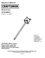
Operator’s Manual
Use QR Code to download the iQMS362i
Operator’s Manual in your language.
Please read the operator’s manual
carefully and make sure you understand
the instructions before using the machine.
Utilisez le code QR pour télécharger le manuel
d’utilisation de l’iQMS362i dans votre langue.
Utilizzare il codice QR per scaricare il manuale
dell’operatore iQMS362i nella propria lingua
Gebruik de QR-code om de iQMS362i
bedieningshandleiding in uw taal te downloaden
Brug QR-kode til at downloade
brugervejledningen til iQMS362i på dit sprog
Verwenden Sie den QR-Code, um das iQMS362i-
Benutzerhandbuch in Ihrer Sprache herunterzuladen