1
3
2
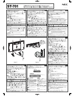
Using the cut out templates and a level, make a cut
into the wall surface at the head end (location of
power source) and the installation location.
Tools Required:
- #2 Phillips Screwdriver
- Precision Slotted Screwdriver
- Level
- Pencil
- Drywall Saw
Parts:
A. Retainer
B. Fascia
C. Hardware
D. Wall Plate
E. Power Supply
F. Mounting Back Box
G. USB Electronics Board
H. Cut Out Template
(a) Connect the 2-pin connectors to the ends of the
power wire and ensure that the hot and ground
configuration is the same on both sides. (b) Fit the
mounting back box into the wall cavity.
See reverse side for more.
33-5915
Run power wire from head end to installation location.
We recommend 16 AWG 2 conductor which will
provide power up to 200 feet from installation
location. Wire size chart on iportmusic.com.
Control Mount Air
Quickstart Guide
70095
HEAD END
INSTALLATION
LOCATION
a.
a.
b.
A.
B.
D.
E.
F.
H.
G.
Full manual available at
iportmusic.com