IONIT Networks LLC
•
5700 Post Rd, Suite 10
•
East Greenwich, RI 02818
•
(401) 244-7404
•
www.ionitnetworks.com
Site Installation Instructions for
ION-9503 Remote Burner Monitoring Kit
Version 1.0 – 12/1/2016
Prior to beginning installation, please scan the QR code to the left, or
download and print the most current instructions from our site here:
http://www.ionitnetworks.com/pdf/ion-9503-install-guide.pdf. Then, please
read through the entire set of instructions and verify that you have all
of the items needed for installation.
The IONIT Networks Burner Network
Module kit is designed to provide remote
monitoring capabilities of the Beckett 7505 GeniSys controller.
(1)
ION-7500 Burner Network Module (BNM)
(2)
ION-7500 BNM magnetic mounting bracket assembly
(3)
ION-7500 BNM interface cable for use with Beckett 7505 controller
(4)
ION-9401 Broadband Internet Hub Receiver, power supply, Ethernet cable
Screw driver (Philips or Slotted)
Smart phone with Internet connectivity
Electrical grease
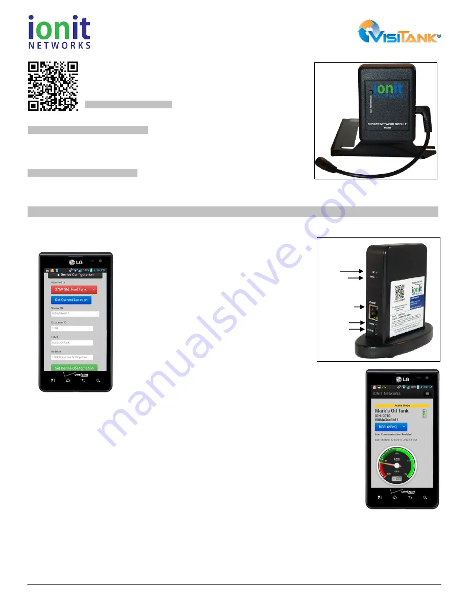
Install Hub: Find a suitable location for the IONIT Hub. Connect the USB power supply securely to the Hub, and plug the AC cord into an
un-switched AC outlet. The OK (top) and Power (bottom) LED indicators on will light green and the Status (middle) LED will flash red to
indicate that the device is ready (figure 3).
1.
Setup Hub: Using your smart phone, scan the QR code on the Hub. When prompted log
into your IONIT Networks account (click “Remember Me”).
Click ‘+Device Configuration’ button, then scroll down.
Next, click ‘Get Current Location’ (figure 4) to use your
phone’s GPS to get your position (ensure your GPS is
turned on). Next, enter any other details that uniquely
identify this device for this customer (e.g. Customer ID or
a Customer Label such as Mr. Jones House). Lastly, click
the ‘Set Device Configuration’ button to save all your
inputs.
2.
Mount the BNM:
Locate the BNM so at least the top half
of the enclosure reaches above the boiler enclosure. This
will help optimize the signal transmission from the BNM to
the hub. Prior to mounting the BNM magnets to the boiler
enclosure, apply a very thin layer of silicone RTV to the
surface where the magnets will attach and let it cure for
~15 minutes. This will help ensure that the BNM stays put
and doesn’t shift around over time.
3.
Route the Interface Cable:
Carefully route and secure the cable where
it won’t come into contact with any hot surfaces, won’t get snagged or be in
the way of the service technician, and looks like the installer takes pride in
their work.
4.
Connect Interface Cable: Apply oxidation barrier grease to the BNM-Beckett adaptor 4-pin 0.100” (J4)
socket receptacle, filling the receptacle holes. Insert the adaptor into the “COMM1” connector on the Beckett
control observing the ‘This Side UP’ label on the adaptor board. Liberally apply oxidation barrier grease to
the 1/8” plugs on the cable and insert the plugs into the adaptor board and BNM.
5.
Set up the BNM: Using your smart phone, scan the QR code on the BNM and assign the device to the
customer site.
6.
Verify Signal Strength: Press the “Fast Report Mode” button the on the BNM to observe RSSI on the
mobile app to ensure strong signal (Figure 5). The gauge will display the signal strength between the BNM
and the Hub. Ensure the ‘Last Update’ date and time is current. If the time is not current, or the signal
strength is not in the green zone (between -100db and -20 db), then you do not have good signal and will
need to move the Hub or install a repeater to increase the range of the signal. Be careful where you place
the Hub. Obstructions like metal filing cabinets and other objects can reduce the signal strength. Once the
RSSI indicator is in the green zone, place the Hub there.
7.
Test-Fire the Boiler: Test-fire the boiler through two cycles to verify operation. Test cycles can be as short as 30 seconds each.
8.
Verify Install: Using your smart phone, scan the QR code found on the BNM can confirm the readings are current by observing the Last
Update time.
Installation has been successful!
Components Included in ION-7500 Kit
Tools and Optional Test Equipment
Intended Use of Equipment
Installation Steps
OK LED
STATUS LED
ETHERNET PORT
POWER LED
POWER PORT
(3)
(5)
(4)