background image

Table of Contents

1

Overview  

  ........................................................................................................................................................................................................................................................................................................................

2

Getting Started  

  ..........................................................................................................................................................................................................................................................................................................

3

Hardware Basics  

  .....................................................................................................................................................................................................................................................................................................

4

Connecting to Your PC  

  ...................................................................................................................................................................................................................................................................................

5

Connecting to Your Vehicle  

  ..........................................................................................................................................................................................................................................................................

6

ValueCAN Connection  

  ...........................................................................................................................................................................................................................................................................

8

neoVI Blue Connection  

  .........................................................................................................................................................................................................................................................................

10

neoVI FIRE / RED Connection  

  .........................................................................................................................................................................................................................................................

12

neoVI Yellow  

  .........................................................................................................................................................................................................................................................................................

14

Application Software  

  ....................................................................................................................................................................................................................................................................................

15

Hardware Configuration  

  ..............................................................................................................................................................................................................................................................................

17

Firmware Updates  

  ...............................................................................................................................................................................................................................................................................

18

In-vehicle Networks  

  ...........................................................................................................................................................................................................................................................................................

19

CAN networks  

  .................................................................................................................................................................................................................................................................................................

20

High Speed CAN  

  .................................................................................................................................................................................................................................................................................

21

Medium Speed CAN  

  ...........................................................................................................................................................................................................................................................................

22

Single Wire CAN  

  .................................................................................................................................................................................................................................................................................

23

Low Speed Fault Tolerant CAN  

  ........................................................................................................................................................................................................................................................

24

CAN Baud Rates and Bit Timing  

  .....................................................................................................................................................................................................................................................

25

Bit Timing Calculator  

  ...................................................................................................................................................................................................................................................................

26

Terminating a Dual Wire CAN Network  

  .........................................................................................................................................................................................................................................

27

Terminating a Low Speed Fault Tolerant CAN Network  

  ............................................................................................................................................................................................................

28

J1850 VPW (Class 2)  

  ..................................................................................................................................................................................................................................................................................

29

J1850 PWM (Ford PWM)  

  ..........................................................................................................................................................................................................................................................................

31

J1708  

  ..................................................................................................................................................................................................................................................................................................................

32

UART/ISO9141/KW2K/LIN  

  .......................................................................................................................................................................................................................................................................

34

UART Timing  

  ........................................................................................................................................................................................................................................................................................

35

Initialization Waveforms  

  ....................................................................................................................................................................................................................................................................

36

Error Checking  

  .....................................................................................................................................................................................................................................................................................

37

Local Interconnect Network (LIN)  

  ...................................................................................................................................................................................................................................................

38

LIN Slave Table  

  ...........................................................................................................................................................................................................................................................................

39

Hardware Features  

  ............................................................................................................................................................................................................................................................................................

Summary of Contents for neoVI

Page 1: ... vehicle Networks 19 CAN networks 20 High Speed CAN 21 Medium Speed CAN 22 Single Wire CAN 23 Low Speed Fault Tolerant CAN 24 CAN Baud Rates and Bit Timing 25 Bit Timing Calculator 26 Terminating a Dual Wire CAN Network 27 Terminating a Low Speed Fault Tolerant CAN Network 28 J1850 VPW Class 2 29 J1850 PWM Ford PWM 31 J1708 32 UART ISO9141 KW2K LIN 34 UART Timing 35 Initialization Waveforms 36 Err...

Page 2: ...ngs 51 neoVI FIRE RED 52 General Purpose IO 54 Specifications 56 Hardware Settings 57 LED Blinking 59 neoVI Yellow 60 General Purpose IO 62 Specifications 63 Hardware Settings 57 LED Blinking 64 ValueCAN 3 65 General Purpose IO 66 Specifications 67 Related Info 68 SAE OBD Book 69 Internet Resources 70 Glossary 71 Contact ...

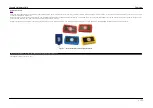
Page 3: ...hrough a 9 pin DSUB connector neoVI and ValueCAN devices can simultaneously read and transmit messages on all of its connected networks time stamp events and transfer the messages to the PC Hardware configuration can be done in Vehicle Spy or through the use of a hardware explorer The hardware explorers allows you to setup baud rates enable disable networks and control device behavior Figure 1 Int...

Page 4: ...ling the neoVI device on USB Next verify that you have the following minimum system requirements One free USB port Windows XP SP3 Vista 7 8 8 1 or 10 Windows RT is not supported If Vehicle Spy 3 is installed the hardware drivers are also installed When a device is plugged in Windows should recognize it and finish the driver install Installation Support If you have any problems installing neoVI or ...

Page 5: ...CAN devices the following steps are needed 1 connect to your PC 2 Connect to your vehicle or device 3 setup the device 4 use application software to do your task neoVI Documentation C Copyright 2000 2019 Intrepid Control Systems Inc Last Update Thursday July 09 2009 Intrepid Hardware Help Hardware Basics 3 71 ...

Page 6: ...nnected to the PC Windows will ask for drives Drivers for the hardware can be found in two locations The Vehicle Spy 3 installation will install the drivers for the hardware Drivers can also be found on the CD that ships with the hardware neoVI Documentation C Copyright 2000 2019 Intrepid Control Systems Inc Last Update Thursday July 09 2009 Intrepid Hardware Help Connecting to Your PC 4 71 ...

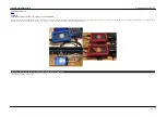
Page 7: ...der the dash board figure 1 Figure 1 The J1962 Connector is usually located under the dash board Here we show the connector on a 1999 GM Saturn SL The device pin out depends on the type of hardware you are connecting and the cable you have To see the pin out for your hardware select your hardware type below ValueCAN3 neoVI Blue neoVI RED neoVI FIRE neoVI Yellow neoVI Documentation C Copyright 2000...

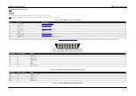
Page 8: ... Electrical Positive Supply 6 5 40 VDC Vehicle interface connectors can be purchased for the ValueCAN 3 For a complete list please see Intrepid Control Systems website The tables below describe two of the commonly used cables for the ValueCAN 3 Figure 1 The OBD II J1962 Connector Vehicle End View Table 2 The ValueCAN 3 OBDII Connector Pin Description Pin OBDII Pin ValueCAN 3 Name 6 7 CAN 1 High 14...

Page 9: ...neoVI Documentation C Copyright 2000 2019 Intrepid Control Systems Inc Last Update Wednesday January 09 2013 Intrepid Hardware Help ValueCAN Connection 7 71 ...

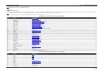
Page 10: ... Bi directional Line K 9 MISC 3 Miscellaneous Signal 3 10 MISC 4 Miscellaneous Signal 4 11 MISC 5 Miscellaneous Signal 5 12 MISC 6 Miscellaneous Signal 6 13 PWR GND Electrical Ground 14 HS CAN H High Speed CAN High 15 HS CAN L High Speed CAN Low 16 MS CAN H Medium Speed CAN High 17 MS CAN L Medium Speed CAN Low 18 LIN LIN 19 J1708 H J1708 High 20 J1708 L J1708 Low 21 MISC 1 Miscellaneous Signal 1 ...

Page 11: ...AN L 17 12 Discretionary 13 Discretionary 14 Discretionary GMLAN HS CAN L HS CAN L 15 15 L line of ISO 9141 2 ISO L 7 16 Un switched Vehicle Battery Positive VBATT 25 Discretionary means that the J1979 specification leaves this pin for use by the manufacturer neoVI Documentation C Copyright 2000 2019 Intrepid Control Systems Inc Last Update Thursday July 09 2009 Intrepid Hardware Help neoVI Blue C...

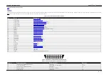
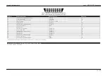
Page 12: ... Speed CAN High 6 MS CAN L Medium Speed CAN Low 7 ISO L UART ISO9141 Keyword Line L 8 ISO K LIN 1 UART ISO9141 Keyword Bi directional Line K 9 DBG CLK Not Used 10 MISC 1 Miscellaneous Signal 1 11 MISC 2 Miscellaneous Signal 2 12 DBG Data Not Used 13 PWR GND Electrical Ground 14 HS CAN H High Speed CAN High 15 HS CAN L High Speed CAN Low 16 HS CAN 2 H High Speed CAN 2 High 17 HS CAN 2 L High Speed ...

Page 13: ... Line of ISO 9141 2 ISO K 8 8 Discretionary 9 Discretionary GM ALDL HS CAN 3 H 19 10 line of SAE J1850 HS CAN 3 L 20 11 Discretionary GMLAN MS CAN L MS CAN L 6 12 Discretionary HS CAN 2 H 16 13 Discretionary HS CAN 2 L 17 14 Discretionary GMLAN HS CAN L HS CAN L 15 15 L line of ISO 9141 2 ISO L 7 16 Un switched Vehicle Battery Positive VBATT 25 Discretionary means that the J1979 specification leav...

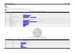
Page 14: ...hield Shield 8 V BATT Electrical Positive Supply 6 32 VDC 9 MISC DIO 2 Miscellaneous Signal 2 10 J1939 2 L CAN 2 L ISO K High Speed CAN Low UART ISO9141 Keyword Bi directional Line K 11 MISC DIO 3 Miscellaneous Signal 3 12 J1939 1 L CAN 1 L High Speed CAN Low 13 J1939 1 H CAN 1 H High Speed CAN High 14 J1708 L J1708 Low 15 J1708 H J1708 High Figure 1 The J1939 RP1210 Connector Vehicle End View Tab...

Page 15: ...9 J 10 High Speed CAN 2 Low neoVI Documentation C Copyright 2000 2019 Intrepid Control Systems Inc Last Update Thursday July 09 2009 Intrepid Hardware Help neoVI Yellow 13 71 ...

Page 16: ...f a full version of Vehicle Spy is not purchased a limited free version is included with the hardware This software lets you do the basics view message traffic and generate it Finally you can write your own application software neoVI includes an API for you to write your own neoVI applications with LabVIEW Visual Basic Borland C Builder LabWindows CVI or Visual C More information on the API includ...

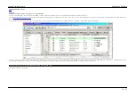
Page 17: ...is done through Intrepid Hardware Explorer This can be found in Vehicle Spy This is done by clicking the Setup Hardware Button or by selecting Setup then Hardware from the menu bar Figure 1 Clicking on the Hardware Setup button will bring up the Hardware Explorer figure 2 Figure 1 Network Setup SpreadSheet Intrepid Hardware Help Hardware Configuration 15 71 ...

Page 18: ...ly stored in the device The status window figure 2 bubble 2 notifies you if there are any issues talking to the hardware The firmware versions are shown under Firmware figure 2 bubble 4 Device settings can be set to defaults by clicking on the Load Defaults button figure 2 bubble 5 in the upper right neoVI Documentation C Copyright 2000 2019 Intrepid Control Systems Inc Last Update Thursday July 0...

Page 19: ...as Your Current Firmware When you connect to your hardware neoVI Hardware Explorer will list the current firmware in the neoVI device Figure 1 Bubble 4 If the firmware does not match the firmware in the software the version number will be flagged red If automatic firmware updates are disabled firmware can be uploaded using the Manual Reflash button After updating the devices firmware check your ne...

Page 20: ...ith Single Wire Transceiver Low Speed Fault Tolerant CAN neoVI Blue neoVI Red and neoVI FIRE CAN Network with Low Speed Fault Tolerant Transceiver J1850 VPW Class 2 neoVI Blue neoVI FIRE and neoVI Yellow J1850 VPW Network Transceiver J1850 PWM Ford SCP neoVI Blue J1850 PWM Network Transceiver ISO9141 Keyword 2K UART LIN neoVI Blue neoVI Red neoVI FIRE and neoVI Yellow UART network transceiver J170...

Page 21: ...ly with no error frames generated or acknowledges Loopback Blue Only No Network operation All messages transmitted are seen as received messages Listen All Except Blue No Network operation All messages transmitted are seen as received messages All messages are received regardless of errors in frame Disable No Network operation Figure 1 You can select the CAN controller mode in the neoVI Explorer n...

Page 22: ...te bit timing and CAN device mode This channel is functionality equivalent to the medium speed channel except for that the neoVI circuits for high speed are optimized According to the ISO11898 specification the ends of the CAN network cabling should be terminated This is described in a separate topic neoVI Documentation C Copyright 2000 2019 Intrepid Control Systems Inc Last Update Wednesday March...

Page 23: ...and CAN device mode This channel is functionality equivalent to the high speed channel except for that the neoVI circuits for the high speed channel are optimized According to the ISO11898 specification the ends of the CAN network cabling should be terminated This is described in a separate topic neoVI Documentation C Copyright 2000 2019 Intrepid Control Systems Inc Last Update Thursday July 09 20...

Page 24: ... mode and 3 high speed mode The default baud rate is used for normal and high voltage modes For the high speed mode you need to specify an additional baud rate this is done on the High Speed Mode panel neoVI provides two modes for the high speed setting one is used for monitoring high speed and the other is to operate as a test tool GMW3089 requires a test tool to switch in a specified test tool r...

Page 25: ...ike all CAN Channels this channel has programmable baud rate bit timing and CAN device mode The Low Speed Fault Tolerant CAN network requires termination with specific resistors This is described in a separate topic neoVI Documentation C Copyright 2000 2019 Intrepid Control Systems Inc Last Update Wednesday March 11 2009 Intrepid Hardware Help Low Speed Fault Tolerant CAN 23 71 ...

Page 26: ...w in figure 1 When you click Edit you will see the CAN Bit Timing Dialog figure 2 This dialog allows you to enter the CNF1 CNF2 CNF3 parameters for the MCP2510 CAN controller Intrepid Control Systems provides an additional software utility to help you figure out these values This utility is the MCP2510 Bit timing calculator you can launch this utility by clicking Launch Bit Timing Calculator Figur...

Page 27: ...p is to adjust the various parameters of the bit timing These include propagation delay phase 1 segment width phase 2 segment width and synchronization jump width The actual bit timing is displayed graphically screen 2 Screen 2 Adjustment of various bit timing parameters click for larger image The calculator will check your setup versus different rules for the various timing When your setup checks...

Page 28: ...N network to be terminated with a 120 ohm resistor Typically if you are connecting to a existing CAN network these termination resistors will be present If you are building a test network you may have to install these resistors neoVI Documentation C Copyright 2000 2019 Intrepid Control Systems Inc Last Update Thursday July 09 2009 Intrepid Hardware Help Terminating a Dual Wire CAN Network 26 71 ...

Page 29: ...d 500 ohms neoVI ships with 510 ohm resistors installed The termination resistors are installed in sockets on the neoVI printed circuit board They can be replaced easily Please see the hardware settings topic for information on how to change the termination resistors Please see the TJA1054 data sheet and related application notes for further information on Low Speed Fault Tolerant CAN network term...

Page 30: ...ocol does not use a specific J1850 protocol chip it generates the VPW symbols with a software peripheral There are no settings for this network neoVI Documentation C Copyright 2000 2019 Intrepid Control Systems Inc Last Update Wednesday March 11 2009 Intrepid Hardware Help J1850 VPW Class 2 28 71 ...

Page 31: ... function read data message parameters These are setup in figure 1 bubble 5 If you want to handle a function read data message check the number 1 or 2 and enter the function code These settings are entered in Lookup Table 2 of the LBCC device You can set the actual data for the function code with the LBCC Set FRead data neoVI virtual network command You can setup the LBCC look up table 1 figure 2 ...

Page 32: ...Figure 2 LBCC Lookup Table 1 setup neoVI Documentation C Copyright 2000 2019 Intrepid Control Systems Inc Last Update Thursday July 09 2009 Intrepid Hardware Help J1850 PWM Ford PWM 30 71 ...

Page 33: ...Applies to neoVI Blue and neoVI Yellow There are no settings for this network neoVI Documentation C Copyright 2000 2019 Intrepid Control Systems Inc Last Update Wednesday March 11 2009 Intrepid Hardware Help J1708 31 71 ...

Page 34: ...ge for the K and L line of VBATT In neoVI Blue the pull up resistor can also be changed Please see the Hardware Settings topic for more information on changing these items Please note that the factory default pull up voltage is VBATT with a pull up resistor of 510 ohms Figure 1 neoVI implements a hardware level shifter for each K and L line As shown in figure 2 there are many settings you can adju...

Page 35: ...e 2 There are many settings for UART Communications neoVI Documentation C Copyright 2000 2019 Intrepid Control Systems Inc Last Update Thursday July 09 2009 Intrepid Hardware Help UART ISO9141 KW2K LIN 33 71 ...

Page 36: ...iptions of timing parameters in ISO UART Timing Parameter Parameter Name Description Rx Inner Frame Spacing Receive Inter frame Separation neoVI determines when a message ends using this parameter If no data byte has been received within this period the end of message is signaled Tx Inner Frame Spacing Transmit Inter frame Separation This is the delay the transmitter will wait between two message ...

Page 37: ...n for example neoVI supports the standard initializations like Fast Init and Five Baud Also neoVI also offers a custom initialization because there has been a variety of initialization implementations For custom initializations you can have a 16 step waveform This is defined in the custom initialization table in hardware explorer Each step can last up to 32 767 seconds and can control both the K a...

Page 38: ...essages and the checking of it on the reception of messages This maybe useful for a UART protocol that doesn t use the checksum or calculates it differently A parity setting is also available if your network requires this Figure 1 The standard checksum for ISO communications can be disabled Parity can also be added if needed neoVI Documentation C Copyright 2000 2019 Intrepid Control Systems Inc La...

Page 39: ...KWord 2K UART LIN options Set the Mode to LIN Mode and the Rx Transceiver to LIN Also make sure the baud rate is correct for your network Figure 1 Figure 1 LIN mode is entered via the neoVI Explorer To Enable LIN on a neoVI FIRE neoVI Red and neoVI Yellow is done in Hardware Explorer by Selecting the channel under network Enables and then setting the proper baud rate for that LIN channel Figure 2 ...

Page 40: ...ed by a master message request Data in the internal Slave Table can updated by resending the slave message in your software application When a master request is received by the hardware the latest data for that ID in the LIN Slave table will be sent neoVI Documentation C Copyright 2000 2019 Intrepid Control Systems Inc Last Update Monday June 01 2009 Intrepid Hardware Help LIN Slave Table 38 71 ...

Page 41: ...se of the differences in hardware these sections are split up between the different hardware types neoVI Blue neoVI RED neoVI FIRE neoVI Yellow ValueCAN3 neoVI Documentation C Copyright 2000 2019 Intrepid Control Systems Inc Last Update Thursday July 09 2009 Intrepid Hardware Help Hardware Features 39 71 ...

Page 42: ...is section also contains the neoVI theory of operation The hardware features discussed in this section include the following 1 neoVI LED 2 General Purpose IO 3 DAQ Pacer Clock 4 Specifications 5 Hardware Settings neoVI Documentation C Copyright 2000 2019 Intrepid Control Systems Inc Last Update Thursday July 09 2009 Intrepid Hardware Help neoVI Blue 40 71 ...

Page 43: ...er section Figure 1 the neoVI block diagram click for larger image Main 51 µController The Main 51 µController figure 2 is responsible for collecting messages from the Main PIC µController and processing them Normally when neoVI is used as a PC interface this means sending them to the PC via USB or RS232 It also could store the messages on it s MMC multimedia card storage device It could also proc...

Page 44: ...nt CAN networks The CAN protocol IC is the MCP2510 IC from Microchip Technology Each protocol chip is connected to the appropriate physical layer for that CAN network All status and control signals for each physical layer are mapped to internal µController pins This allows complete software control of the CAN functionality Figure 4 The neoVI CAN Networks LBCC Protocol IC The LBCC protocol is a pro...

Page 45: ...erent in frame responses which cause incompatibilities between J1850 VPW protocol ICs The ISO UART section is very flexible The K and L lines have software controlled transmit enable lines allowing many different variants of UART or ISO9141 communications including Tx on L Rx on K Tx and Rx on K Tx on K and L and Rx on K The MISC signals contain four 10 bit analog inputs and one external wake up i...

Page 46: ...ED works can be set in neoVI explorer Table 1 The LED Operating Modes LED Operating Mode Description Standard Mode The standard LED setting This setting will cause the LED to toggle between Red and off every 104 ms You can also control the LED with scripts using this setting Display MISC3 Displays the state of the MISC3 pin It will display green if the pin is on otherwise it will be off Display MI...

Page 47: ...o analog inputs 2 analog input on MISC 3 and 3 analog inputs on MISC 3 6 When setting up MISC3 only the sampling rate will be once per millisecond If the setting is for MISC3 6 the sample rate will be every four milliseconds General IO Reporting You can setup the general IO to be automatically reported to the host in neoVI explorer figure 2 You can setup the general IO to be reported at an interva...

Page 48: ...ve the neoVI device automatically report the state of MISC IO pins neoVI Documentation C Copyright 2000 2019 Intrepid Control Systems Inc Last Update Tuesday January 08 2013 Intrepid Hardware Help General Purpose IO 46 71 ...

Page 49: ... samples Step 5 Send the Start DAQ neoVI Device Virtual Network Command to start the clock neoVI will send a neoVI Device Network message time stamped when the DAQ Clock was started Step 6 Record network messages from the neoVI until the DAQ card has acquired the proper number of samples Step 7 After the DAQ Card completes its scan assemble the DAQ card data and neoVI message buffer in to one buff...

Page 50: ... VSI Interface via RS232 Networks General Time stamping to accuracy of 100uS on CAN networks J1708 network and Ford SCP network 250 µs on Class 2 J1850 VPW and ISO KW2K Timestamp rollover is greater than 1 year Simultaneous operations on all networks with aggregate bandwidth performance of 2 mega baud over USB Transmit message double buffering on all networks allows back to back message transmissi...

Page 51: ...alization waveforms 0 5 ms resolution Software selectable baud rate Socket selectable pull up resistor on both K and L lines Jumper selectable pull up voltage either 5V or Battery K and L have software controlled transmit enable lines allowing many different variants of UART or ISO9141 communications including Tx on L Rx on K Tx and Rx on K Tx on K and L and Rx on K Ford SCP SAE J1850 PWM Dual BCC...

Page 52: ...ion A Insert two 0 25 W resistors end to end in the sockets See terminating a Low Speed Fault Tolerant CAN network for details K and L line pull up resistors B Insert two 0 25 W resistors end to end with desired pull up values 510 Ohms are the factory default J1850 PWM LBCC C Insert two 0 5 W resistors end to end with the desired termination 160 Ohms are the factory default LIN Master Resistor D I...

Page 53: ...are not in vehicle networks This section details them The hardware features discussed in this section include the following 1 General Purpose IO and 2 Specifications neoVI Documentation C Copyright 2000 2019 Intrepid Control Systems Inc Last Update Wednesday July 15 2009 Intrepid Hardware Help neoVI FIRE RED 51 71 ...

Page 54: ...ded to sink current Analog Inputs MISC pins 3 through 6 can be setup as analog inputs To enable an analog input you can select Analog inputs from the Initial Setup window General IO Reporting You can setup the general IO to be automatically reported to the host in neoVI 3G Explorer figure 2 You can setup the general IO to be reported at an interval or based on digital inputs changing figure 2 bubb...

Page 55: ...ve the neoVI device automatically report the state of MISC IO pins neoVI Documentation C Copyright 2000 2019 Intrepid Control Systems Inc Last Update Tuesday August 10 2010 Intrepid Hardware Help General Purpose IO 53 71 ...

Page 56: ...9 Low Speed Fault Tolerant CAN Physical Layer TJA1054A 1 Dedicated Single Wire CAN Physical Layer GMW3089 SAE J2411 MC33897 CAN 2 0B Active Up to 1 M Bit Software Selectable Baud Rate auto baud capable Capable of generating and detecting error frames With firmware update Logic Analysis of CAN Waveform with 25 nanosecond resolution With firmware update Graphical Bit Time Baud Rate Calculator Listen...

Page 57: ...ansmission Option available in CGI Simulation Toolkit neoVI Documentation C Copyright 2000 2019 Intrepid Control Systems Inc Last Update Monday December 14 2009 Intrepid Hardware Help Specifications 55 71 ...

Page 58: ...settings Table 1 Hardware Settings in the neoVI device Setting Bubble in Figure 1 Instructions Low Speed Fault Tolerant CAN Termination A Insert two 0 25 W resistors end to end in the sockets See terminating a Low Speed Fault Tolerant CAN network for details Figure 1 The neoVI has three settings inside the box neoVI Documentation C Copyright 2000 2019 Intrepid Control Systems Inc Last Update Thurs...

Page 59: ... blinking pattern can be changed by VehicleScape Logging or in a function block VehicleScape Standalone Logging Flashing Red Green blinking VehicleScape Standalone loggingschangesthe blinking pattern of the LEDs The Red LEDwill flash at a constant rate while the Green will blinkwith data being saved to Micro SDcard VehicleScape Standalone Logging Post trigger Flashing Red quickly blinking Green Th...

Page 60: ...Last Update Friday September 13 2013 Intrepid Hardware Help LED Blinking 58 71 ...

Page 61: ...ures which are not in vehicle networks The hardware features discussed in this section include the following 1 General Purpose IO and 2 Specifications neoVI Documentation C Copyright 2000 2019 Intrepid Control Systems Inc Last Update Wednesday July 15 2009 Intrepid Hardware Help neoVI Yellow 59 71 ...

Page 62: ...nalog inputs from the Initial Setup window General IO Reporting You can setup the general IO to be automatically reported to the host in neoVI 3G Explorer figure 2 You can setup the general IO to be reported at an interval or based on digital inputs changing figure 2 bubble 1 The report will be sent to the host as a neoVI Device Virtual Network message When reporting based on interval is selected ...

Page 63: ...Last Update Tuesday January 08 2013 Intrepid Hardware Help General Purpose IO 61 71 ...

Page 64: ...Selectable Baud Rate auto baud capable Capable of generating and detecting error frames Logic Analysis of CAN Waveform with 25 nanosecond resolution Graphical Bit Time Baud Rate Calculator Listen only mode support Unterminated network detection J1708 High precision time capture of J1708 bus events Software selectable parameters including baud rate SAE J1708 Physical layer K and L Line 1x LIN Local...

Page 65: ...1 Hardware Settings in the neoVI device Setting Bubble in Figure 1 Instructions K and L line pull up resistors A Insert two 0 25 W resistors end to end with desired pull up values 510 Ohms are the factory default Figure 1 The K Line pull ups neoVI Documentation C Copyright 2000 2019 Intrepid Control Systems Inc Last Update Thursday July 09 2009 Intrepid Hardware Help Hardware Settings 63 71 ...

Page 66: ...urable features which are not in vehicle network The General Purpose IO and Specifications sections cover the non network features neoVI Documentation C Copyright 2000 2019 Intrepid Control Systems Inc Last Update Wednesday July 15 2009 Intrepid Hardware Help ValueCAN 3 64 71 ...

Page 67: ...Intrepid Hardware Help General Purpose IO 65 71 ...

Page 68: ...Intrepid Hardware Help Specifications 66 71 ...

Page 69: ...ion details some resources to help learn more about them The resources are the following 1 SAE OBD Book 2 Internet Resources and 3 Glossary neoVI Documentation C Copyright 2000 2019 Intrepid Control Systems Inc Last Update Wednesday April 11 2001 Intrepid Hardware Help Related Info 67 71 ...

Page 70: ...ss B Data Communication Network Messages Part 2 Data Parameter Definitions Class B Data Communication Network Messages Part 3 Frame IDs for Single Byte Forms of Headers Class B Data Communication Network Messages Message Definitions for Three Byte Headers and Bibliography of Related SAE Technical Papers This book contains all of the following specifications J1850 J1962 J1979 and other diagnostic s...

Page 71: ...anization fro Standardization www iso ch US EPA OBD II Site www epa gov oms obd htm CARB California Air Resources Board www arb ca gov neoVI Silicon Vendors Microchip Technology MCP2510 CAN Controller www microchip com Philips Dual Wire 82C251 and Low Speed Fault Tolerant TJA1054 Transceivers www philips com Infineon Single Wire CAN Transceiver TLE6255 www infineon com Motorola J1850 VPW Physical ...

Page 72: ...ponses are also available in the protocol J1939 Specification for communications for Heavy Truck and Bus based on CAN messages using a 29 bit Arb ID J1962 Specification detailing the diagnostic connector found in North American vehicles This connector is also called the ODB II connector and the ALDL connector J1979 Specifications which detail ODB II test modes and data This includes requesting val...

Page 73: ...Research Park Dr Madison Heights MI 48071 USA ph 586 731 7950 fax 586 731 2274 email website www intrepidcs com neoVI Documentation C Copyright 2000 2019 Intrepid Control Systems Inc Last Update Monday September 16 2013 Intrepid Hardware Help Contact 71 71 ...

Reviews: