International Harvester Company 15D-1, Operator'S Manual
The International Harvester Company 15D-1 Operator's Manual is available for free download on manualshive.com. This manual provides detailed instructions on how to operate and maintain the 15D-1 model, ensuring optimal performance. Download your copy now and keep your equipment running smoothly.
Share
Download


Reviews:
No comments
Related manuals for 15D-1
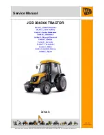
354
Brand: jcb Pages: 21

'16' Series
Brand: Mahindra Pages: 140

STS 10 Combo
Brand: Hagie Pages: 149

TOSAPRATO TP60
Brand: GOLDONI Pages: 30

PRO-TILL 10
Brand: Degelman Pages: 35

CT325
Brand: Ransomes Pages: 72

UTC920
Brand: Uni-ram Pages: 9

Proxima Plus Series
Brand: Zetor Pages: 254

AlpS 271
Brand: SaMASZ Pages: 42

COMMANDER 4500
Brand: Hardi Pages: 170

12244
Brand: Original Tractor Cabs Pages: 13

FCX24
Brand: FMS Pages: 43

HELT151B
Brand: Husqvarna Pages: 18
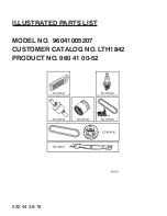
960 41 00-52
Brand: Husqvarna Pages: 18

96043014300
Brand: Husqvarna Pages: 19
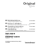
EUROTOP 620 N
Brand: Poettinger Pages: 55

Mikasa MVH-702DRSC
Brand: MULTIQUIP Pages: 58

Rammax RX1575
Brand: MULTIQUIP Pages: 96


