

#34-0000-0201 Rev- 09-04
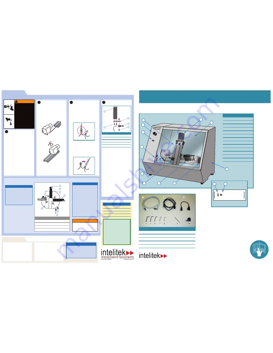
Accessory kit components
Qu
ic
k-
St
ar
t I
ns
ta
ll
Gu
id
e
spectraLIGHT 0400
Turning Center
Item # Description
1
Enclosure
2
Safety shield
3
X axis motor
4
Cross slide
5
Emergency stop switch
6
Spindle speed switch
7
Safety shield interlock switch
8
Chuck
9
Tool holder
10
Tailstock
11
Z axis motor
12
Controller box power switch
13
Controller box lock out switch
Controller Box
12
13
Machine Components
Item #
Description
1
25 pin cable
2
AC Power supply cord
3
Accessory adapter cable
4
Hex key (5/32")
5
Hex key (9/64")
6
Hex key (1/8")
7
Hex key (3/32")
8
Hex key (5/64")
9
Spindle locking pin
10
Indexable tool holder
www.intelitek.com
Tool Turret
Tool Turret
Accessories
Accessories
Using the Tool Turret
NOTE:
The tool turret will support up to
eight different tools at one time. The
tool positions are numbered on the
tooling plate:
Slots 1, 3, and 7:
Hold right-hand, left-hand, profiling
and external threading tools.
Mount tools in these positions with
the cutting face down.
Holes 2, 4, 6 and 8:
Hold boring, drilling and internal
threading tools.
Tool position 5
is for the cut off tool.
CAUTION
Before cutting, make sure that each
tool has sufficient clearance so it does
not ram into the chuck or workpiece
when changing tools.
1
Push in the Emergency Stop button and
raise the safety shield.
2
If a tool is currently present:
• Loosen the set screws holding the tool using
the 1/8" allen wrench.
• Remove the tool and shim (if a shim is
present).
3
Insert the tool (and shim if necessary) into
the turret.
4
Tighten the two set screws into the side of
the tool.
The tool tip and spindle centerline must
lie on the same plane. If necessary, use
shims to mount tools in the turret. This is
essential to achieve tight machine
tolerances and surface finish.
The tool tip must not extend more than
1.125" from the tooling plate to avoid
tool chatter.
NOTE:
To mount a tool:
Tool turret diagram
Item #
Description
A
Tool turret plate
B
Tool
C
Set screws
D
1.125" max dimension
A
D
C
B
1 Loosen the four hex-head screws
mounted in the turret body enough to
allow the t-nuts to enter the slots on the
cross slide.
2 Insert the t-nuts into the cross slide slots
from the bottom and slide the turret up
towards the top of the cross slide.
3 Tighten the four hex head screws using
the hex key. Do not over-tighten.
4 Remove the cap from the turret port on
the rear wall inside the enclosure.
5 Attach the 9-pin connector from the
turret to the turret port inside the
enclosure.
2
Mount the turret
1 Turn the turning center onto its side
(spindle side down) so you can safely
reach the connectors beneath the Z-axis
drive motor.
2 Locate the connector with one blue wire
and one brown wire protruding from one
end, and one black wire and one white
wire protruding from the other end.
3 Unclip the connector that attaches the
black and white wires to the brown and
blue wires.
4 Locate the loose connector with two blue
wires and one red wire with a yellow stripe.
5 Connect the black and white connector to
the loose connector.
3
Re-wire the limit switch
Black
White
Blue
Blue
Red/Yellow
Brown
Black
White
Blue
Blue
Red/Yellow
Brown
1 Locate the Z limit switch on the lathe bed.
The limit switch is fastened to the bed by
an adjustable bracket.
2 Loosen the thumbscrew to remove the
adjustable bracket and the limit switch
from the lathe bed.
3 Remove the screws that hold the limit
switch onto the adjustable bracket. Retain
the screws; you will use them again later in
this procedure.
4 Locate the extension bracket and 3/16 pan
head screws in the tool turret package.
5 Using the 3/16 pan head screws, attach the
extension bracket to the adjustable
bracket.
6 Attach the limit switch to the opposite end
of the extension bracket, using the original
screws that you retained earlier.
7 Return the adjustable bracket to its original
position on the bed and tighten the
thumbscrew.
4
Attach the Z-axis Limit switch
extension bracket
5
4
3
1
2
Item Description
1
Adjustable limit switch bracket
2
3/16" pan head screws (2)
3
Extension bracket
4
Limit switch
5
Original limit switch screws (2)
Install the Tool Turret
Install the Tool Turret
Rotating shaft!
Moving cutting tools!
The automatic tool turret
ships with tools installed.
Handle cutting tools carefully.
Before opening the safety
shield:
• Press in the Emergency Stop
button
• Wait until all motion has
stopped
WARNING
To install the turret, first jog the cross slide to
an accessible position.
1 Turn on the computer and the controller box.
2 Be sure the safety shield is down and the
emergency stop button is pulled out.
3 Open the control software. (Select Start >
Programs >CNCBase)
4 If the Jog control Panel is not visible, click
View > Jog Control to open the Jog
Control panel.
5 Click the top X axis button to jog the cross
slide upward on the X axis to the limit of
travel.
6 Click the right Y axis button to jog the
cross slide to the right so that the turret
will clear the spindle.
7 Shut down the software, computer and
controller box.
1
Jog the cross slide
Technical Support:
Phone
(800) 221-2763
Fax
(603) 625-2137
Web
www.intelitek.com
Before contacting intelitek
make sure you have the following
information:
• The product serial number located on
the rear of the machine
• The name of the owner of the product
• Your computer specifications /
documentation
• Notes on any Control Program error
messages
• Access to the hardware and software
components of your system
Installing the Optional Air Chuck
1
Plug the power cord from the solenoid valve
on the vise into the receptacle end of the
accessory port adapter cable.
2
Remove the protective cap from the plug
end of the accessory port adapter cable and
attach the cable to the ACC 1 port on the
rear panel of the Controller Box.
Installing Other Accessories
To connect a second 120VAC accessory:
1
Plug the accessory's power cord into the
receptacle end of another accessory port
adapter cable.
2
Insert the plug end of the cable into the ACC
2 port on the Controller Box.
NOTE:
Accessories must not exceed 3 amps maximum
current draw.
The TTL I/O connector on the rear panel of the
Controller Box allows interfacing with an I/O
device such as a robot.
9
4
3
2
10
11
8
7
5
6
1


