Infranor SMT-BD2, Manual
The Infranor SMT-BD2 user manual is available for download absolutely free from our website. This comprehensive manual provides step-by-step instructions and detailed information to help you optimize the performance of your Infranor SMT-BD2 product. Enhance your experience by accessing the manual at manualshive.com.
Share
Download


Reviews:
No comments
Related manuals for SMT-BD2

III
Brand: Fender Pages: 20

BUX 2.8
Brand: RAM Pages: 13

953.032
Brand: Power Dynamics Pages: 20

HA43
Brand: Rolls Pages: 2

1407A POWER AMPLIFIER
Brand: Altec Lansing Pages: 17

Riot GT380
Brand: Boss Audio Systems Pages: 8

Nemesis N12
Brand: Eden Pages: 6

The Interfacer
Brand: GOODWOOD AUDIO Pages: 4

EVO 100-1
Brand: PrimaLuna Pages: 20

Thunder 50 Type E322
Brand: Engl Pages: 6

Mini-Pre Vacuum Tube Microphone PreAmp
Brand: dbx Pages: 12

3W Amplified Phone Neckloop
Brand: Spy Earpice Pages: 3

KVMP CM1164
Brand: ATEN Pages: 2

JAS Bravo 1.1 LE
Brand: Jas Audio Pages: 9

Marley
Brand: M2TECH Pages: 32

basX A-100
Brand: Emotiva Pages: 28

Syn Tech 4.075
Brand: Macrom Pages: 30
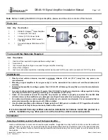
DBA8-19
Brand: INTELIGAIN Pages: 3


