industrie technik Evolution FH-2xxSH1 series, User Manual
The Industrie Technik Evolution FH-2xxSH1 series comes with a comprehensive User Manual to assist you in harnessing the full potential of this remarkable product. You can easily download the manual for free from our website, ensuring a seamless experience with your FH-2xxSH1 series product.
Share
Download


Reviews:
No comments
Related manuals for Evolution FH-2xxSH1 series

Smart Thermostat
Brand: tado° Pages: 10
9306
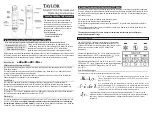
Brand: Taylor Pages: 6

3M-50
Brand: Filtrete Pages: 18

KTsmart
Brand: Unical Pages: 48

ProAccurate DTF572
Brand: CDN Pages: 4

HCTB-3040
Brand: Omega Engineering Pages: 31

VA-IH008
Brand: Vava Pages: 5

103818
Brand: haupa Pages: 11

ALFA 52-VS
Brand: VDH Pages: 4

798314
Brand: Brookstone Pages: 8

javelin
Brand: lavatools Pages: 13

TDS23-AC2
Brand: Beok Controls Pages: 2

Wi-Time WiFi
Brand: Seitron Pages: 8

DCPA80BC
Brand: Seitron Pages: 66

TGP51WIFI
Brand: Beok Controls Pages: 4

FlexStat
Brand: KMC Controls Pages: 60

S1-TBEU22P7S
Brand: 1 Source Pages: 17

62 MAX
Brand: Fluke Pages: 22


