IMC Networks PoE Giga-MiniMc, Operation Manual
The IMC Networks PoE Giga-MiniMc is a high-performance network device that enables the efficient transmission of data and power over Ethernet. To ensure optimal use, users can easily access the comprehensive Operation Manual. Download the manual for free at manualshive.com for detailed instructions on installation, configuration, and troubleshooting.
Share
Download


Reviews:
No comments
Related manuals for PoE Giga-MiniMc

VEGAPOINT 11
Brand: Vega Pages: 28

PSA10
Brand: PKP Pages: 11

MUH44A-H2
Brand: Woxcon Pages: 42

SIL IntelliPoint RF S*R*L Series
Brand: Ametek Pages: 93

PFS4226-24ET-240
Brand: Dahua Pages: 3

SE-DVI-8-LC
Brand: Cypress Pages: 4

13811
Brand: TCi Pages: 11

AT-HDDVI1616-AM
Brand: Atlona Pages: 15

C11-082-31-120
Brand: AETEK Pages: 2

KCB-121
Brand: KTI Pages: 16

L8-WP FLOTECT
Brand: Dwyer Instruments Pages: 2

D4D-1520R
Brand: Omron Pages: 13

S5850-24S2C
Brand: FS Pages: 43

PCCS9RW
Brand: Whelen Engineering Company Pages: 5

HXL5
Brand: Hendrickson Pages: 16
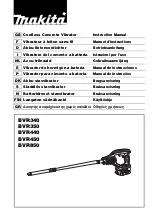
Makstar BVR340
Brand: Makita Pages: 40

KS220M
Brand: TP-Link Pages: 35

SW10
Brand: Marmitek Pages: 28


