IFM Electronic efector 800 VSE002, Operating Instructions Manual
The IFM Electronic efector 800 VSE002 Operating Instructions Manual is the comprehensive user guide for this high-quality product. You can easily download this manual for free from manualshive.com, ensuring you have all the information needed to operate your efector device efficiently and effectively.
Share
Download


Reviews:
No comments
Related manuals for efector 800 VSE002

LAD-SAF
Brand: 3M Pages: 88

Mini Rad-D
Brand: D-tect Systems Pages: 4

NEXT PLUS Series
Brand: Visonic Pages: 4

SPM Flow Line
Brand: Weir Pages: 42

JA-83P
Brand: jablotron Pages: 2

CSS300
Brand: RAM Pages: 38

Profi+ KH 2927-2
Brand: Powerfix Pages: 53

Deckvest Cento
Brand: Spinlock Pages: 7

PCE-186 CB
Brand: PCE Health and Fitness Pages: 17

R718B2
Brand: netvox Pages: 11

HMDS1040 - Xanboo Home Monitoring
Brand: Motorola Pages: 10

HMDS1040 - Xanboo Home Monitoring
Brand: Motorola Pages: 2

LCM
Brand: Tractel Pages: 36

BL-REF-2
Brand: bloom lab Pages: 41
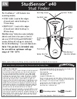
StudSensor e40
Brand: Zircon Pages: 6

CT-SMEF2001-SNB
Brand: CAP-HOMEY Pages: 4

49061003
Brand: nordlux Pages: 24

Busch Watchdog 6131 102-500 PM/A Series
Brand: ABB Pages: 164


