background image


uIB X-210-C V-N2600 E mbedded S ys tem 

P age i 

Us er Manual 

,   

MODE L :  

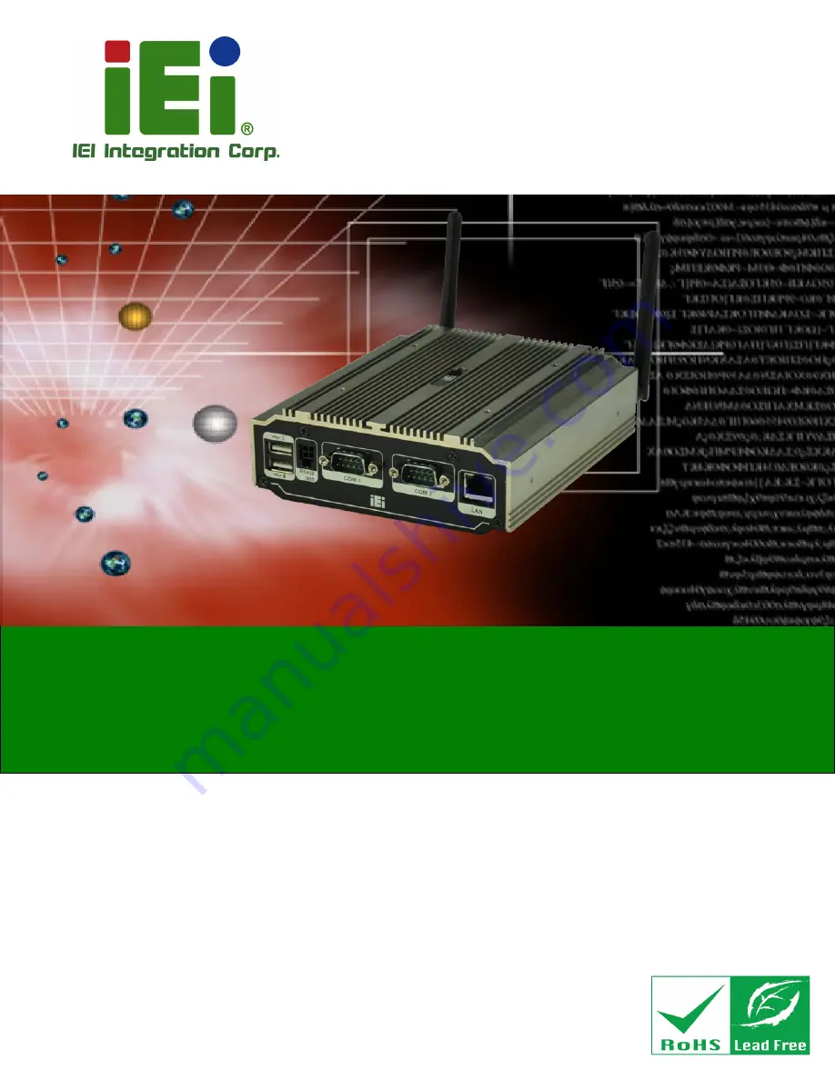
uIB X-210-C V-N2600 S eries  

F anles s  E mbedded S ys tem with Intel®  Atom™   N2600 

DC  1.6G Hz, Intel®  NM10 chips et, P re-ins talled 2G B  DDR 3 

memory,  VG A,  HDMI, G bE , F our US B  2.0, 

Three C OM and R oHS  C ompliant 

R ev. 1.02 – 14 J une 2018 

Summary of Contents for uIBX-210-CV-N2600 Series

Page 1: ...e i Us er Manual MODE L uIB X 210 CV N2600 S eries Fanles s E mbedded S ys tem with Intel Atom N2600 DC 1 6GHz Intel NM10 chips et Pre ins talled 2GB DDR 3 memory VGA HDMI GbE Four US B 2 0 Three COM and R oHS Compliant R ev 1 02 14 J une 2018 ...

Page 2: ...age ii R evis ion Date Version Changes 14 June 2018 1 02 Add Table 3 1 RS 422 485 Serial Port Pinouts Add Table 3 2 RS 422 485 Connector Pinouts DB 9 28 February 2013 1 01 Update Section 2 3 Packing List 27 December 2012 1 00 Initial release ...

Page 3: ... damages arising out of the use or inability to use the product or documentation even if advised of the possibility of such damages This document contains proprietary information protected by copyright All rights are reserved No part of this manual may be reproduced by any mechanical electronic or other means in any form without prior written permission of the manufacturer TR ADE MAR K S All regis...

Page 4: ...y CAUTION Cautionary messages should be heeded to help reduce the chance of losing data or damaging the product NOTE These messages inform the reader of essential but non critical information These messages should be read carefully as any directions or instructions contained therein can help avoid making mistakes HOT S UR FACE This symbol indicates a hot surface that should not be touched without ...

Page 5: ... LIST 11 3 INSTALLATION 12 3 1 INSTALLATION PRECAUTIONS 13 3 2 INSTALLATION AND CONFIGURATION STEPS 13 3 3 WI FI ANTENNA INSTALLATION WI FI MODEL ONLY 13 3 4 AT ATX MODE SELECTION 14 3 4 1 AT Power Mode 15 3 4 2 ATX Power Mode 15 3 5 RESET THE SYSTEM 15 3 6 POWERING ON THE SYSTEM 16 3 7 MOUNT THE SYSTEM 16 3 7 1 Wall Mount 17 3 7 2 VESA mount 75 19 3 7 3 VESA mount 100 22 3 8 EXTERNAL PERIPHERAL I...

Page 6: ...JSATA Connector JSATA2 39 4 2 6 Power LED Connector PWRLED1 39 4 2 7 USB 2 0 Connector USB4_5 40 4 2 8 SATA Connector S_ATA1 40 4 2 9 SATA Power Connector CN1 40 4 3 EXTERNAL INTERFACE PANEL CONNECTORS 41 4 3 1 Audio Jack JAUDIO1 41 4 3 2 Ethernet Connector LAN1 41 4 3 3 HDMI Connector HDMI1 42 4 3 4 Power Connector DC_JACK1 42 4 3 5 RS 232 Serial Ports COM1 COM2 42 4 3 6 RS 422 485 Serial Port CO...

Page 7: ... 57 6 3 ADVANCED 58 6 3 1 ACPI Configuration 58 6 3 2 RTC Wake Settings 59 6 3 3 CPU Configuration 61 6 3 4 SATA Configuration 62 6 3 5 USB Configuration 63 6 3 6 F81866 Super IO Configuration 64 6 3 6 1 Serial Port n Configuration 65 6 3 7 F81866 H W Monitor 68 6 3 8 Serial Port Console Redirection 69 6 3 8 1 Console Redirection Settings 70 6 4 IEI FEATURE 72 6 5 CHIPSET 73 6 5 1 Host Bridge Conf...

Page 8: ...UTIONS 90 B 1 1 General Safety Precautions 90 B 1 2 Anti static Precautions 91 B 1 3 Product Disposal 92 B 2 MAINTENANCE AND CLEANING PRECAUTIONS 92 B 2 1 Maintenance and Cleaning 93 B 2 2 Cleaning Tools 93 C BIOS MENU OPTIONS 94 D WATCHDOG TIMER 97 E HAZARDOUS MATERIALS DISCLOSURE 100 ...

Page 9: ...re 3 8 Panel PC VESA 75 mm 19 Figure 3 9 Mount Kit Installation 20 Figure 3 10 Slide the System 20 Figure 3 11 Mount Kit Screws 21 Figure 3 12 Stand Installation 21 Figure 3 13 Panel PC VESA 100 mm 22 Figure 3 14 100 mm to 75 mm Adapter 22 Figure 3 15 Mount Kit Installation 23 Figure 3 16 Slide the System 23 Figure 3 17 Mount Kit Screws 24 Figure 3 18 Stand Installation 24 Figure 3 19 Peripheral C...

Page 10: ...Removal 47 Figure 5 2 HDD Bracket Retention Screws 48 Figure 5 3 HDD Bracket 48 Figure 5 4 HDD Retention Screws 49 Figure 5 5 Remove the old HDD 49 Figure 5 6 uIBX 210 CV N2600 SO DIMM Socket Location 50 Figure 5 7 DDR3 SO DIMM Module Installation 51 Figure 5 8 uIBX 210 CV N2600 SO DIMM Socket Location 52 Figure 5 9 Removing the Antennas 52 Figure 5 10 Releasing the WLAN Card 53 Figure 5 11 Removi...

Page 11: ...e 4 7 Power LED Connector Pinouts PWRLED1 39 Table 4 8 USB 2 0 Connector Pinouts USB4_5 40 Table 4 9 SATA Connector Pinouts S_ATA1 40 Table 4 10 SATA Power Connector Pinouts CN1 40 Table 4 11 Rear Panel Connectors 41 Table 4 12 Audio Jack Pinouts JAUDIO1 41 Table 4 13 Ethernet Connector Pinouts LAN1 42 Table 4 14 HDMI Connector HDMI1 Pinouts 42 Table 4 15 Power Connector Pinouts DC_JACK1 42 Table ...

Page 12: ...IO Configuration 64 BIOS Menu 9 Serial Port n Configuration Menu 65 BIOS Menu 10 Hardware Health Configuration 68 BIOS Menu 11 Serial Port Console Redirection 69 BIOS Menu 12 Console Redirection Settings 70 BIOS Menu 13 iEi Feature 72 BIOS Menu 14 Chipset 73 BIOS Menu 15 Northbridge Chipset Configuration 74 BIOS Menu 16 Integrated Graphics 75 BIOS Menu 17 Southbridge Chipset Configuration 76 BIOS ...

Page 13: ...uIB X 210 CV N2600 E mbedded S ys tem Page 2 Chapter 1 1 Introduction ...

Page 14: ...el DDR3 SDRAM SO DIMM module up to 2 GB The uIBX 210 CV N2600 supports a 2 5 SATA HDD with up to 3 Gb s data transfer rate Three serial ports and four external USB 2 0 ports ensure simplified connectivity to a variety of external peripheral devices 1 2 Model Variations The model variations of the uIBX 210 CV N2600 series are listed below Models CPU Wireless uIBX 210 CV N2600 2GB R10 Intel Atom N26...

Page 15: ...ith four USB one VGA one HDMI three COM and audio 1 4 Technical S pecifications The uIBX 210 CV N2600 technical specifications are listed in 331HTable 1 2 Chas s is Form Factor uIBX Color Silver Dimens ions 146 6mm x 132mm x 45 2mm Chas s is Cons truction Aluminum Alloy ABS Motherboard CPU Intel N2600 1 6GHz dual core processor Chips et Intel NM10 B IOS UEFI BIOS Memory 2GB DDR3 800MHz N2600 suppo...

Page 16: ... LED Power LED indicator Front I Os 1 x HDMI 1 x VGA 2 x USB port 1 x Mic in 1 x Line out R ear I Os 2 x USB port 2 x RS 232 COM 1 COM 2 1 x RS 422 485 COM 3 1 x RJ 45 LAN Interior E xpans ions 1 x PCIe Mini slot reserved for Wi Fi B utton S witch Reset switch AT ATX switch Power Button Power Power S upply AT ATX support DC IN 12V 5A Locking type DC in jack on board rear side Power Cons umption 12...

Page 17: ...soft CE 6 0 Table 1 2 Technical Specifications 1 5 Front Panel The front panel of the uIBX 210 CV N2600 has the following features Figure 1 2 2 x RS 232 serial port connectors COM1 COM2 1 x RS 422 485 serial port connector COM3 1 x RJ 45 LAN connector 2 x USB 2 0 connectors Figure 1 2 uIBX 210 CV N2600 Front Panel 1 6 R ear Panel The rear panel of the uIBX 210 CV N2600 has the following features F...

Page 18: ...edded S ys tem Page 7 1 x AT ATX Switch 1 x HDD LED 1 x HDMI port 1 x Line out 1 x Mic 1 x Power button 1 x Power LED 1 x Reset button 2 x USB 2 0 connectors 1 x 12 V DC IN 1 x VGA port Figure 1 3 uIBX 210 CV N2600 Rear Panel ...

Page 19: ...uIB X 210 CV N2600 E mbedded S ys tem Page 8 1 7 Dimens ions The physical dimensions are shown below Figure 1 4 Physical Dimensions mm ...

Page 20: ...uIB X 210 CV N2600 E mbedded S ys tem Page 9 Chapter 2 2 Unpacking ...

Page 21: ...c wristband Wearing a simple anti static wristband can help to prevent ESD from damaging the board Self grounding Before handling the board touch any grounded conducting material During the time the board is handled frequently touch any conducting materials that are connected to the ground Use an anti static pad When configuring the uIBX 210 CV N2600 place it on an antic static pad This reduces th...

Page 22: ...t the IEI reseller or vendor you purchased the uIBX 210 CV N2600 from or contact an IEI sales representative directly To contact an IEI sales representative please send an email to 165Hsales iei com tw The uIBX 210 CV N2600 is shipped with the following components Quantity Item and Part Number Image 1 uIBX 210 CV N2600 1 1 x Adaptor 12V 5A 1 1 x Screw set Table 2 1 Package List Contents ...

Page 23: ...uIB X 210 CV N2600 E mbedded S ys tem Page 12 Chapter 3 3 Ins tallation ...

Page 24: ...rsonnel Maintenance upgrades or repairs may only be carried out by qualified personnel who are familiar with the associated dangers Grounding The uIBX 210 CV N2600 should be properly grounded The voltage feeds must not be overloaded Adjust the cabling and provide external overcharge protection per the electrical values indicated on the label attached to the back of the uIBX 210 CV N2600 3 2 Ins ta...

Page 25: ... 3 4 AT ATX Mode S election AT or ATX power mode can be used on the uIBX 210 CV N2600 The selection is made through an AT ATX switch located on the rear panel Figure 3 2 To select AT mode or ATX mode follow the steps below S tep 1 Locate the AT ATX switch on the rear panel Figure 3 2 Figure 3 2 AT ATX Switch Location S tep 2 Adjust the AT ATX switch S tep 0 ...

Page 26: ...ing shop flow 3 4 2 ATX Power Mode With the ATX mode selected the uIBX 210 CV N2600 panel PC goes in a standby mode when it is turned off The panel PC can be easily turned on via network or a power switch in standby mode Remote power control is perfect for advertising applications since the broadcasting time for each panel PC can be set individually and controlled remotely Other possible applicati...

Page 27: ...t button S tep 0 3 6 Powering On the S ys tem To power on the system follow the steps below S tep 1 Press the power button on the front panel Figure 3 4 S tep 2 Once turned on the power LED should light up Figure 3 4 Power Button Location 3 7 Mount the S ys tem The mounting methods are described below ...

Page 28: ...wall for the bracket retention screws S tep 4 Align the wall mounting bracket screw holes with the pilot holes S tep 5 Secure the mounting bracket to the wall by inserting the retention screws into the four pilot holes and tightening them Figure 3 5 Figure 3 5 Wall mounting Bracket S tep 6 Insert the four mounting screws provided in the package into the four screw holes on the bottom panel of the ...

Page 29: ...ts securely in the slotted holes Figure 3 6 Ensure that all four of the mounting screws fit snuggly into their respective slotted holes Figure 3 6 Chassis Support Screws S tep 9 Secure the uIBX 210 CV N2600 by fastening the retention screw of the wall mounting bracket Figure 3 7 S tep 0 NOTE In the diagram below the bracket is already installed on the wall ...

Page 30: ...V N2600 E mbedded S ys tem Page 19 Figure 3 7 Secure the uIBX 210 CV N2600 3 7 2 VE S A mount 75 To mount the embedded system onto a panel PC VESA 75 mm please follow the steps below Figure 3 8 Panel PC VESA 75 mm ...

Page 31: ...CV N2600 E mbedded S ys tem Page 20 S tep 1 Install the mount kit on the back of the panel PC Figure 3 9 Mount Kit Installation S tep 2 Slide the uIBX 210 CV N2600 into the mount kit Figure 3 10 Slide the System ...

Page 32: ...600 E mbedded S ys tem Page 21 S tep 3 Fasten the four screws on the mount kit Figure 3 11 Mount Kit Screws S tep 4 Attach the uIBX 210 CV N2600 to the stand using four retention screws Figure 3 12 Stand Installation ...

Page 33: ...ount 100 To mount the embedded system onto a panel PC VESA 100 mm please follow the steps below Figure 3 13 Panel PC VESA 100 mm S tep 1 If the mounting pattern on the panel PC is VESA 100 mm then the adapter must be attached Figure 3 14 100 mm to 75 mm Adapter ...

Page 34: ...s tem Page 23 S tep 2 Fasten the mount kit onto the VESA mount 100 mm to 75 mm adapter on the back of the panel PC Figure 3 15 Mount Kit Installation S tep 3 Slide the uIBX 210 CV N2600 into the mount kit Figure 3 16 Slide the System ...

Page 35: ...it Figure 3 17 Mount Kit Screws S tep 5 Attach the uIBX 210 CV N2600 to the stand using four retention screws Figure 3 18 Stand Installation 3 8 E xternal Peripheral Interface Connectors The following external peripheral devices can be connected to the external peripheral interface connectors ...

Page 36: ... cable connector Serial devices USB devices To install these devices connect the corresponding cable connector from the actual device to the corresponding uIBX 210 CV N2600 external peripheral interface connector making sure the pins are properly aligned Figure 3 19 Peripheral Connectors Front Panel ...

Page 37: ...dentify the audio plugs The plugs on your home theater system or speakers may not match the colors on the rear panel If audio plugs are plugged into the wrong jacks sound quality will be very bad S tep 2 Plug the audio plugs into the audio jacks Plug the audio plugs into the audio jacks If the plugs on your speakers are different an adapter will need to be used to plug them into the audio jacks Li...

Page 38: ...ght 3 8 2 HDMI Device Connection The HDMI connector transmits a digital signal to compatible HDMI display devices such as a TV or computer screen To connect the HDMI cable to the uIBX 210 CV N2600 follow the steps below S tep 1 Locate the HDMI connector The location is shown in Chapter 1 S tep 2 Align the connector Align the HDMI connector with the HDMI port Make sure the orientation of the connec...

Page 39: ... connector is being inserted with the right way up 3 8 3 LAN Connection There is one external RJ 45 LAN connector The RJ 45 connector enables connection to an external network To connect a LAN cable with an RJ 45 connector please follow the instructions below S tep 1 Locate the RJ 45 connectors The location of the LAN connector is shown in Chapter 1 S tep 2 Align the connectors Align the RJ 45 con...

Page 40: ...onnection There are two RS 232 DB 9 connectors of the uIBX 210 CV N2600 for serial device connection Follow the steps below to connect a serial device to the DB 9 connector of the uIBX 210 CV N2600 S tep 1 Locate the DB 9 connector The locations of the DB 9 connectors are shown in Chapter 1 S tep 2 Insert the serial connector Insert the DB 9 connector of a serial device into the DB 9 connector on ...

Page 41: ...2 485 S erial Port Connection There is one RS 422 485 serial port of the uIBX 210 CV N2600 for serial device connection Follow the steps below to connect a serial device to the RS 422 485 serial port of the uIBX 210 CV N2600 S tep 1 Locate the RS 422 RS485 connector The location of the RS 422 485 connector is shown in Figure 1 2 S tep 2 Connect the RS 422 485 cable to the RS 422 485 connector The ...

Page 42: ...onnector to the external interface by tightening the two retention screws on either side of the connector The pinouts of the RS 422 485 serial port is shown below Figure 3 26 RS 422 485 Serial Port Connector Pin Description Pin Description 1 RXD485 _R 3 TXD485 _R 2 RXD485 _R 4 TXD485 _R Table 3 1 RS 422 485 Serial Port Pinouts The DB 9 connector pinouts are listed below Figure 3 27 RS 422 485 Seri...

Page 43: ...S option to configure the correspondent serial ports refer to Sections 6 3 6 1 3 for detailed information 3 8 6 US B Device Connection There are four USB 2 0 connectors on the uIBX 210 CV N2600 To connect a USB device please follow the instructions below S tep 1 Locate the USB connectors The locations of the USB connectors are shown in Chapter 1 S tep 2 Align the connectors Align the USB device co...

Page 44: ...CRT or VGA monitor To connect a monitor to the uIBX 210 CV N2600 please follow the instructions below S tep 1 Locate the female DB 15 connector The location of the female DB 15 connector is shown in Chapter 1 S tep 2 Align the VGA connector Align the male DB 15 connector on the VGA screen cable with the female DB 15 connector on the uIBX 210 CV N2600 S tep 3 Insert the VGA connector Once the conne...

Page 45: ...face by tightening the two retention screws on either side of the connector 3 9 Driver Download To download drivers from IEI Resource Download Center follow the steps below S tep 5 Go to https download ieiworld com Type uIBX 210 CV N2600 and press Enter S tep 6 All product related software utilities and documentation will be listed You can choose Driver to filter the result ...

Page 46: ...O file or click the small arrow to find an individual driver and click the file name to download NOTE To install software from the downloaded ISO image file in Windows 8 8 1 or 10 double click the ISO file to mount it as a virtual drive to view its content On Windows 7 system an additional tool such as Virtual CD ROM Control Panel from Microsoft is needed to mount the file ...

Page 47: ...uIB X 210 CV N2600 E mbedded S ys tem Page 36 4 S ys tem Motherboard Chapter 4 ...

Page 48: ...oard The Pin 1 locations of the on board connectors are also indicated in the diagram below Figure 4 1 System Motherboard 4 2 Internal Peripheral Connectors The table below shows a list of the internal peripheral interface connectors on the system motherboard Pinouts of these connectors can be found in the following sections Connector Type Label Battery connector 2 pin wafer BAT1 BIOS programming ...

Page 49: ..._5 SATA 3Gb s drive connector 7 pin SATA connector S_ATA1 SATA power connector 2 pin wafer CN1 Table 4 1 Peripheral Interface Connectors 4 2 1 B attery Connector B AT1 4 2 2 B IOS Programming Connector S PI1 PIN NO DESCRIPTION PIN NO DESCRIPTION 1 SPI_VCC 2 SPI_CS 0_CN 3 SPI_SO0_CN 4 SPI_CLK0_CN 5 SPI_SI0_CN 6 GND Table 4 3 BIOS Programming Connector Pinouts SPI1 4 2 3 Debug port Connector DE B UG...

Page 50: ...RIPTION PIN NO DESCRIPTION 1 GND 2 12V 3 N C 4 12V 5 N C 6 N C 7 GND 8 5V 9 SATA_RX1 10 5V 11 SATA_RX1 12 5V 13 GND 14 5V 15 SATA_TX1 16 GND 17 SATA_TX1 18 3V 19 GND 20 3V Table 4 6 JSATA Connector Pinouts JSATA2 4 2 6 Power LE D Connector PWR LE D1 PIN NO DESCRIPTION PIN NO DESCRIPTION 1 GND 2 5V Table 4 7 Power LED Connector Pinouts PWRLED1 PIN NO DESCRIPTION 1 SATA_LED 2 5V Table 4 5 HDD LED Co...

Page 51: ...4 USB_PP6 5 USB_PP5 6 USB_PN6 7 GND 8 5V Table 4 8 USB 2 0 Connector Pinouts USB4_5 4 2 8 S ATA Connector S _ATA1 4 2 9 S ATA Power Connector CN1 PIN NO DESCRIPTION 1 GND 2 SATA_TX0 3 SATA_TX0 4 GND 5 SATA_RX0 6 SATA_RX0 7 GND Table 4 9 SATA Connector Pinouts S_ATA1 PIN NO DESCRIPTION 1 5V 2 GND Table 4 10 SATA Power Connector Pinouts CN1 ...

Page 52: ...ector HDMI HDMI1 Power connector Power jack DC_JACK1 RS 232 serial ports DB 9 COM1 COM2 RS 422 485 serial port 4 pin connector COM3 USB 2 0 connectors USB 2 0 port USB0_1 USB2_3 VGA connector DB 15 VGA1 Table 4 11 Rear Panel Connectors 4 3 1 Audio J ack J AUDIO1 PIN NO DESCRIPTION PIN NO DESCRIPTION 1 GND_AUDIO 2 LMIC1 CONN L 3 GND_AUDIO 4 JD_MIC 5 LMIC1 CONN R 22 LFRONT L 23 GND_AUDIO 24 JD_FRONT...

Page 53: ... 3 HDMI_DATA2 4 HDMI_DATA1 5 GND 6 HDMI_DATA1 7 HDMI_DATA0 8 GND 9 HDMI_DATA0 10 HDMI_CLK 11 GND 12 HDMI_CLK 13 NC 14 NC 15 HDMI_SCL 16 HDMI_SDA 17 GND 18 5V 19 HDMI_HPD Table 4 14 HDMI Connector HDMI1 Pinouts 4 3 4 Power Connector DC_J ACK 1 PIN NO DESCRIPTION PIN NO DESCRIPTION 1 VCC12V 2 GND 3 GND Table 4 15 Power Connector Pinouts DC_JACK1 4 3 5 R S 232 S erial Ports COM1 COM2 PIN NO DESCRIPTI...

Page 54: ...85 Serial Port Pinouts COM3 4 3 7 US B 2 0 Connectors US B 0_1 PIN NO DESCRIPTION PIN NO DESCRIPTION 1 5V 2 USB_PN0 3 USB_PP0 4 GND 5 5V 6 USB_PN1 7 USB_PP1 8 GND Table 4 18 USB 2 0 Connectors Pinouts USB0_1 4 3 8 US B 2 0 Connector US B 23 PIN NO DESCRIPTION PIN NO DESCRIPTION 1 5V 2 USB_PN2 3 USB_PP2 4 GND 5 5V 6 USB_PN3 7 USB_PP3 8 GND Table 4 19 USB 2 0 Connector Pinouts USB2_3 4 3 9 VGA Conne...

Page 55: ...GA Connector Pinouts VGA1 4 4 J umper S ettings The jumpers on the system motherboard are listed in Table 4 21 Connector Type Label AT ATX mode select 2 pin header J_AUTOPWR1 Table 4 21 Jumper 4 4 1 AT ATX Mode S elect J umper J _AUTOPWR 1 Pin Description Short AT Mode Open ATX Mode Default Table 4 22 AT ATX Mode Select Jumper Settings J_AUTOPWR1 ...

Page 56: ...uIB X 210 CV N2600 E mbedded S ys tem Page 45 Chapter 5 5 S ys tem Maintenance ...

Page 57: ...c discharge ESD can cause serious damage to electronic components including the uIBX 210 CV N2600 Dry climates are especially susceptible to ESD It is therefore critical that whenever the uIBX 210 CV N2600 is accessed internally or any other electrical component is handled the following anti static precautions are strictly adhered to Wear an anti static wristband Wearing a simple anti static wrist...

Page 58: ...m and serious or fatal injury to the user Before any maintenance procedures are carried out on the system make sure the system is turned off 5 4 R eplacing Components 5 4 1 Hard Dis k Drive HDD R eplacement To replace the hard drive please follow the steps below S tep 1 Remove eight 8 retention screws from the back cover 335HFigure 5 1 Figure 5 1 Retention Screws Removal S tep 2 Remove the back co...

Page 59: ...t retention screws and disconnect the SATA connector JSATA2 as shown in 335HFigure 5 2 Figure 5 2 HDD Bracket Retention Screws S tep 4 Lift the HDD bracket out of the uIBX 210 CV N2600 336HFigure 5 3 Figure 5 3 HDD Bracket S tep 5 Remove the four HDD retention screws 337HFigure 5 3 ...

Page 60: ...ure 5 5 Remove the old HDD S tep 7 Slide the new HDD to the HDD bracket Secure the HDD with the HDD bracket by four HDD retention screws S tep 8 Correctly align the four retention screw holes on the HDD bracket with the retention screw holes on the chassis Insert four previously removed retention screws to secure the HDD bracket to the chassis ...

Page 61: ...1 Remove eight 8 retention screws from the back cover See Section 5 4 1 S tep 2 Remove HDD module See Section 5 4 1 S tep 3 Locate the memory module indicated below Figure 5 6 uIBX 210 CV N2600 SO DIMM Socket Location S tep 4 Remove the DDR3 memory module by pulling both the spring retainer clips outward from the socket S tep 5 Grasp the DDR3 memory module by the edges and carefully pull it out of...

Page 62: ... and secure the DDR3 memory module in the socket Figure 5 7 DDR3 SO DIMM Module Installation S tep 9 Replace the back cover and secure it using eight 8 previously removed retention screws 5 4 3 WLAN Card R eplacement The uIBX 210 CV N2600 has one WLAN card slot To replace the WLAN card follow the instructions below S tep 1 Remove eight 8 retention screws from the back cover See Section 5 4 1 S tep...

Page 63: ...s tem Page 52 Figure 5 8 uIBX 210 CV N2600 SO DIMM Socket Location S tep 4 Disconnect the antenna connectors on the WLAN module Figure 5 9 Figure 5 9 Removing the Antennas S tep 5 Push the two spring clips in to release the WLAN card ...

Page 64: ...t Figure 5 11 Figure 5 11 Removing the WLAN card S tep 7 Install a new WLAN card by inserting the card into the slot at an angle S tep 8 Push the WLAN card down until the spring retainer clips lock into place S tep 9 Connect the antenna connectors on the WLAN module S tep 10 Replace the back cover and secure it using eight 8 previously removed retention screws ...

Page 65: ...uIB X 210 CV N2600 E mbedded S ys tem Page 54 Chapter 6 6 B IOS ...

Page 66: ...ars before the DELETE key is pressed restart the computer and try again 6 1 2 Us ing S etup Use the arrow keys to highlight items press ENTER to select use the PageUp and PageDown keys to change entries press F1 for help and press ESC to quit Navigation keys are shown in K ey Function Up arrow Move to previous item Down arrow Move to next item Left arrow Move to the item on the left hand side Righ...

Page 67: ...t boot after changes to the system configuration is made CMOS defaults Use the jumper described in Chapter 5 6 1 5 B IOS Menu B ar The menu bar on top of the BIOS screen has the following main items Main Changes the basic system configuration Advanced Changes the advanced system settings Chipset Changes the chipset settings Boot Changes the system boot configuration Security Sets User and Supervis...

Page 68: ...Use Tab to switch between Time elements Select Screen Select Item EnterSelect F1 General Help F2 Previous Values F3 Optimized Defaults F4 Save ESC Exit Version 2 14 1219 Copyright C 2011 American Megatrends Inc BIOS Menu 1 Main B IOS Information The BIOS Information lists a brief summary of the BIOS The fields in BIOS Information cannot be changed The items shown in the system overview include BIO...

Page 69: ...ware Aptio Setup Utility Copyright C 2009 American Megatrends Inc Main Advanced Chipset Boot Security Save Exit ACPI Settings RTC Wake Settings CPU Configuration SATA Configuration USB Configuration F81866 Super IO Configuration F81866 H M Monitor Serial Port Console Redirection iEi Feature System ACPI Parameters Select Screen Select Item EnterSelect F1 General Help F2 Previous Values F3 Optimized...

Page 70: ... Megatrends Inc BIOS Menu 3 ACPI Configuration AC PI S leep S tate S 1 CPU S top Clock Use the ACPI Sleep State option to specify the sleep state the system enters when it is not being used S1 CPU Stop Clock DEFAULT The system enters S1 POS sleep state The system appears off The CPU is stopped RAM is refreshed the system is running in a low power mode S3 Suspend to RAM The caches are flushed and t...

Page 71: ... Megatrends Inc BIOS Menu 4 RTC Wake Settings Wake s ys tem with Fixed Time Dis abled Use the Wake system with Fixed Time option to enable or disable the system wake on alarm event Disabled DEFAULT The real time clock RTC cannot generate a wake event Enabled If selected the Wake up every day option appears allowing you to enable to disable the system to wake every day at the specified time Besides...

Page 72: ...ogy and Disabled for other OS OS not optimized for Hyper Threading Technology Select Screen Select Item EnterSelect Change Opt F1 General Help F2 Previous Values F3 Optimized Defaults F4 Save Exit ESC Exit Version 2 14 1219 Copyright C 2011 American Megatrends Inc BIOS Menu 5 CPU Configuration The CPU Configuration menu BIOS Menu 5 lists the following CPU details Processor Type Lists the CPU proce...

Page 73: ...nu 6 to change and or set the configuration of the SATA devices installed in the system Aptio Setup Utility Copyright C 2009 American Megatrends Inc Advanced SATA Mode AHCI SATA Port1 Hitachi HTS543 320 0 Select a configuration for SATA Controller Select Screen Select Item EnterSelect F1 General Help F2 Previous Values F3 Optimized Defaults F4 Save ESC Exit Version 2 14 1219 Copyright C 2011 Ameri...

Page 74: ...neral Help F2 Previous Values F3 Optimized Defaults F4 Save ESC Exit Version 2 14 1219 Copyright C 2011 American Megatrends Inc BIOS Menu 7 USB Configuration US B Devices The USB Devices Enabled field lists the USB devices that are enabled on the system Legacy US B S upport E nabled Use the Legacy USB Support BIOS option to enable USB mouse and USB keyboard support Normally if this option is not e...

Page 75: ... controllers parallel ports and serial ports Aptio Setup Utility Copyright C 2009 American Megatrends Inc Advanced F81866 Super IO Configuration F81866 Super IO Chip F81866 Serial Port 1 Configuration Serial Port 2 Configuration Serial Port 3 Configuration Set Parameters of Serial Port 1 COMA Select Screen Select Item EnterSelect F1 General Help F2 Previous Values F3 Optimized Defaults F4 Save ESC...

Page 76: ...Values F3 Optimized Defaults F4 Save ESC Exit Version 2 14 1219 Copyright C 2011 American Megatrends Inc BIOS Menu 9 Serial Port n Configuration Menu 6 3 6 1 1 S erial Port 1 Configuration S erial Port E nabled Use the Serial Port option to enable or disable the serial port Disabled Disable the serial port Enabled DEFAULT Enable the serial port Change S ettings Auto Use the Change Settings option ...

Page 77: ...rt option to enable or disable the serial port Disabled Disable the serial port Enabled DEFAULT Enable the serial port Change S ettings Auto Use the Change Settings option to change the serial port IO port address and interrupt address Auto DEFAULT The serial port IO port address and interrupt address are automatically detected IO 2F8h IRQ 3 Serial Port I O port address is 2F8h and the interrupt a...

Page 78: ... and interrupt address are automatically detected IO 3E8h IRQ 10 Serial Port I O port address is 3E8h and the interrupt address is IRQ10 IO 3F8h IRQ 10 11 Serial Port I O port address is 3F8h and the interrupt address is IRQ10 11 IO 2F8h IRQ 10 11 Serial Port I O port address is 2F8h and the interrupt address is IRQ10 11 IO 3E8h IRQ 10 11 Serial Port I O port address is 3E8h and the interrupt addr...

Page 79: ...n Megatrends Inc Advanced PC Health Status CPU temperature 44 C System temperature 38 C V_core 1 048 V VCC5 4 940 V Vcc12 11 660 V VDDR 1 512 V VSB5V 5 016 V V3 3S 3 376 V VSB3V 3 360 V VBAT 3 312 V Select Screen Select Item EnterSelect F1 General Help F2 Previous Values F3 Optimized Defaults F4 Save ESC Exit Version 2 14 1219 Copyright C 2011 American Megatrends Inc BIOS Menu 10 Hardware Health C...

Page 80: ...009 American Megatrends Inc Advanced COM1 Console Redirection Disabled Console Redirection Settings COM2 Console Redirection Disabled Console Redirection Settings Console Redirection Enable or Disable Select Screen Select Item EnterSelect F1 General Help F2 Previous Values F3 Optimized Defaults F4 Save ESC Exit Version 2 14 1219 Copyright C 2011 American Megatrends Inc BIOS Menu 11 Serial Port Con...

Page 81: ...t VT100 Extends VT100 to support color function keys etc VT UTF8 Uses UTF8 encoding to map Unicode chars onto 1 or more bytes Select Screen Select Item EnterSelect F1 General Help F2 Previous Values F3 Optimized Defaults F4 Save ESC Exit Version 2 14 1219 Copyright C 2011 American Megatrends Inc BIOS Menu 12 Console Redirection Settings Terminal Type ANS I Use the Terminal Type option to specify t...

Page 82: ...e parity bit that can be sent with the data bits for detecting the transmission errors None DEFAULT No parity bit is sent with the data bits Even The parity bit is 0 if the number of ones in the data bits is even Odd The parity bit is 0 if the number of ones in the data bits is odd Mark The parity bit is always 1 This option does not provide error detection Space The parity bit is always 0 This op...

Page 83: ...d recover system automatically within 10 min when OS crashes Please install Auto Recovery API service before enabling this function Select Screen Select Item EnterSelect Change Opt F1 General Help F2 Previous Values F3 Optimized Defaults F4 Save Exit ESC Exit Version 2 14 1219 Copyright C 2011 American Megatrends Inc BIOS Menu 13 iEi Feature Auto R ecovery Function Dis abled Use the Auto Recovery ...

Page 84: ...in the Chipset BIOS menu may cause the system to malfunction Aptio Setup Utility Copyright C 2011 American Megatrends Inc Main Advanced Chipset Boot Security Save Exit Host Bridge South Bridge Host Bridge Parameters Select Screen Select Item EnterSelect Change Opt F1 General Help F2 Previous Values F3 Optimized Defaults F4 Save Exit ESC Exit Version 2 14 1219 Copyright C 2011 American Megatrends I...

Page 85: ...8 MB Configure Intel IGD Settings Select Screen Select Item EnterSelect Change Opt F1 General Help F2 Previous Values F3 Optimized Defaults F4 Save Exit ESC Exit Version 2 14 1219 Copyright C 2011 American Megatrends Inc BIOS Menu 15 Northbridge Chipset Configuration Memory Information The Memory Information lists a brief summary of the on board memory The fields in Memory Information cannot be ch...

Page 86: ...trends Inc BIOS Menu 16 Integrated Graphics IGFX B oot Type VB IOS Default Use the IGFX Boot Type option to select the display device used by the system when it boots For dual display support select VBIOS Deafult Configuration options are listed below VBIOS Default DEFAULT CRT HDMI CRT HDMI Fixed Graphics Memory S ize 128 MB Use the Fixed Graphics Memory Size option to specify the amount of memory...

Page 87: ...p Utility Copyright C 2009 American Megatrends Inc Main Advanced Chipset Boot Security Save Exit Boot Configuration Bootup NumLock State On Quiet Boot Enabled Launch PXE OpROM Disabled Option ROM Messages Force BIOS UEFI Boot Disabled Boot Option Priorities Boot Option 1 SATA PM Hitachi Hard Drive BBS Prioties Select the keyboard NumLock state Select Screen Select Item EnterSelect F1 General Help ...

Page 88: ...on the keyboard is lit Quiet B oot E nabled Use the Quiet Boot BIOS option to select the screen display when the system boots Disabled Normal POST messages displayed Enabled DEFAULT OEM Logo displayed instead of POST messages Launch PXE OpR OM Dis abled Use the Launch PXE OpROM BIOS option to enable or disable boot option for legacy network devices Disabled DEFAULT Cannot be booted from the legacy...

Page 89: ...devices is enabled Disabled DEFAULT Boot from UEFI devices is disabled B oot Option Priority Use the Boot Option Priority function to set the system boot sequence from the available devices The drive sequence also depends on the boot sequence in the individual device section Hard Drive B B S Priorities Use Hard Drive BBS Priorities option to set the system boot order ...

Page 90: ...d and must be entered to boot or enter Setup In Setup the User will have Administrator rights The password length must be in the following range Minimum length 3 Maximum length 20 Administrator Password User Password HDD Security Configuration HDD0 Hitachi HTS5 Set Administrator Password Select Screen Select Item EnterSelect F1 General Help F2 Previous Values F3 Optimized Defaults F4 Save ESC Exit...

Page 91: ...th Master Password in POST HDD PASSWORD CONFIGURATION Security Supported Yes Security Enabled No Security Locked No Security Frozen No HDD User Pwd Status NOT INSTALLED HDD Master Pwd Status INSTALLED Set User Password Set HDD User Password Advisable to Power Cycle System after Settig Hard Disk Passwords Select Screen Select Item EnterSelect Change Opt F1 General Help F2 Previous Values F3 Optimiz...

Page 92: ...Select Item EnterSelect F1 General Help F2 Previous Values F3 Optimized Defaults F4 Save ESC Exit Version 2 14 1219 Copyright C 2011 American Megatrends Inc BIOS Menu 21 Exit S ave Changes and R es et Use the Save Changes and Reset option to save the changes made to the BIOS options and to exit the BIOS configuration setup program Dis card Changes and R es et Use the Discard Changes and Reset opti...

Page 93: ...em Page 82 S ave as Us er Defaults Use the Save as User Defaults option to save the changes done so far as user defaults R es tore Us er Defaults Use the Restore User Defaults option to restore the user defaults to all the setup options ...

Page 94: ...uIB X 210 CV N2600 E mbedded S ys tem Page 83 Appendix A A R egulatory Compliance ...

Page 95: ... of the Radio Equipment Directive 2014 53 EU English IEI Integration Corp declares that this equipment is in compliance wit the essential requirements and other relevant provisions of Directive 2014 53 EU Български Bulgarian IEI Integration Corp декларира че този оборудване е в съответствие със съществените изисквания и другите приложим правила на Директива 2014 53 EU Česky Czech IEI Integration C...

Page 96: ...osiciones aplicables o exigibles de la Directiva 2014 53 EU Ελληνική Greek IEI Integration Corp ΔΗΛΩΝΕΙ ΟΤΙ ΕΞΟΠΛΙΣΜΟΣ ΣΥΜΜΟΡΦΩΝΕΤΑΙ ΠΡΟΣ ΤΙΣ ΟΥΣΙΩΔΕΙΣ ΑΠΑΙΤΗΣΕΙΣ ΚΑΙ ΤΙΣ ΛΟΙΠΕΣ ΣΧΕΤΙΚΕΣ ΔΙΑΤΑΞΕΙΣ ΤΗΣ ΟΔΗΓΙΑΣ 2014 53 EU Français French IEI Integration Corp déclare que l appareil est conforme aux exigences essentielles et aux autres dispositions pertinentes de la directive 2014 53 EU Italiano Itali...

Page 97: ...nti li hemm fid Dirrettiva 2014 53 EU Magyar Hungarian IEI Integration Corp nyilatkozom hogy a berendezés megfelel a vonatkozó alapvetõ követelményeknek és az 2014 53 EU irányelv egyéb elõírásainak Polski Polish IEI Integration Corp oświadcza że wyrobu jest zgodny z zasadniczymi wymogami oraz pozostałymi stosownymi postanowieniami Dyrektywy 2014 53 EU Português Portuguese IEI Integration Corp decl...

Page 98: ...NG This equipment complies with Part 15 of the FCC Rules Operation is subject to the following two conditions This device may not cause harmful interference and This device must accept any interference received including interference that may cause undesired operation This equipment has been tested and found to comply with the limits for a Class A digital device pursuant to part 15 of the FCC Rule...

Page 99: ...e with the instructions may cause harmful interference to radio communications However there is no guarantee that interference will not occur in a particular installation If this equipment does cause harmful interference to radio or television reception which can be determined by turning the equipment off and on the user is encouraged to try to correct the interference by one of the following meas...

Page 100: ...uIB X 210 CV N2600 E mbedded S ys tem Page 89 B S afety Precautions Appendix A ...

Page 101: ...ever the uIBX 210 CV N2600 is being installed moved or modified Do not apply voltage levels that exceed the specified voltage range Doing so may cause fire and or an electrical shock Electric shocks can occur if the uIBX 210 CV N2600 chassis is opened when the uIBX 210 CV N2600 is running Do not drop or insert any objects into the ventilation openings of the uIBX 210 CV N2600 If considerable amoun...

Page 102: ...ts are handled the following anti static precautions are strictly adhered to Wear an anti static wristband Wearing a simple anti static wristband can help to prevent ESD from damaging any electrical component Self grounding Before handling any electrical component touch any grounded conducting material During the time the electrical component is handled frequently touch any conducting materials th...

Page 103: ...opean Directive 2012 19 EU WEEE and must not be disposed of as domestic garbage EU wide legislation as implemented in each Member State requires that waste electrical and electronic products carrying the mark left must be disposed of separately from normal household waste This includes monitors and electrical accessories such as signal cables or power cords When you need to dispose of your display...

Page 104: ...product specifically designed for the purpose In such case the product will be explicitly mentioned in the cleaning tips Below is a list of items to use when cleaning the uIBX 210 CV N2600 Cloth Although paper towels or tissues can be used a soft clean piece of cloth is recommended when cleaning the uIBX 210 CV N2600 Water or rubbing alcohol A cloth moistened with water or rubbing alcohol can be u...

Page 105: ...uIB X 210 CV N2600 E mbedded S ys tem Page 94 C B IOS Menu Options Appendix B ...

Page 106: ...led 66 Change Settings Auto 66 Serial Port Enabled 67 Change Settings Auto 67 Device Mode RS422 68 PC Health Status 68 Console Redirection 69 Terminal Type ANSI 70 Bits per second 115200 70 Data Bits 8 71 Parity None 71 Stop Bits 1 71 Auto Recovery Function Disabled 72 Memory Information 74 IGFX Boot Type VBIOS Default 75 Fixed Graphics Memory Size 128 MB 75 Bootup NumLock State On 76 Quiet Boot E...

Page 107: ...00 E mbedded S ys tem Page 96 Administrator Password 79 User Password 79 Set User Password 80 Save Changes and Reset 81 Discard Changes and Reset 81 Restore Defaults 81 Save as User Defaults 82 Restore User Defaults 82 ...

Page 108: ...uIB X 210 CV N2600 E mbedded S ys tem Page 97 D Watchdog Timer Appendix D ...

Page 109: ...ate A BIOS function call INT 15H is used to control the Watchdog Timer INT 15H AH 6FH S ub function AL 2 Sets the Watchdog Timer s period BL Time out value Its unit second is dependent on the item Watchdog Timer unit select in CMOS setup Table D 1 AH 6FH Sub function Call sub function 2 to set the time out period of Watchdog Timer first If the time out value is not zero the Watchdog Timer starts c...

Page 110: ...wise the system resets Example program INITIAL TIMER PERIOD COUNTER W_LOOP MOV AX 6F02H setting the time out value MOV BL 05 time out value is 5 seconds INT 15H ADD THE APPLICATION PROGRAM HERE CMP EXIT_AP 1 is the application over JNE W_LOOP No restart the application MOV AX 6F02H disable Watchdog Timer MOV BL 0 INT 15H EXIT ...

Page 111: ...uIB X 210 CV N2600 E mbedded S ys tem Page 100 Appendix E E Hazardous Materials Dis clos ure ...

Page 112: ...s and lamps These components will be separately marked Please refer to the following table Part Name Toxic or Hazardous Substances and Elements Lead Pb Mercury Hg Cadmium Cd Hexavalent Chromium CR VI Polybrominated Biphenyls PBB Polybrominated Diphenyl Ethers PBDE Housing O O O O O O Display O O O O O O Printed Circuit Board O O O O O O Metal Fasteners O O O O O O Cable Assembly O O O O O O Fan As...

Page 113: ...换元件 像是电池或灯管 这些元 件将会单独标示出来 部件名称 有毒有害物质或元素 铅 Pb 汞 Hg 镉 Cd 六价铬 CR VI 多溴联苯 PB B 多溴二苯 醚 PB DE 壳体 O O O O O O 显示 O O O O O O 印刷电路板 O O O O O O 金属螺帽 O O O O O O 电缆组装 O O O O O O 风扇组装 O O O O O O 电力供应组装 O O O O O O 电池 O O O O O O O 表示该有毒有害物质在该部件所有物质材料中的含量均在 SJ T 11363 2006 现由 GB T 26572 2011 取代 标准规定的限量要求以下 X 表示该有毒有害物质至少在该部件的某一均质材料中的含量超出 SJ T 11363 2006 现由 GB T 26572 2011 取代 标准规定的限量要求 ...

Reviews: