background image


TANK-860-HM86  Em b e d d e d   S ys te m  

P a g e   i 

Us e r  Ma n u a l 


MODEL: 

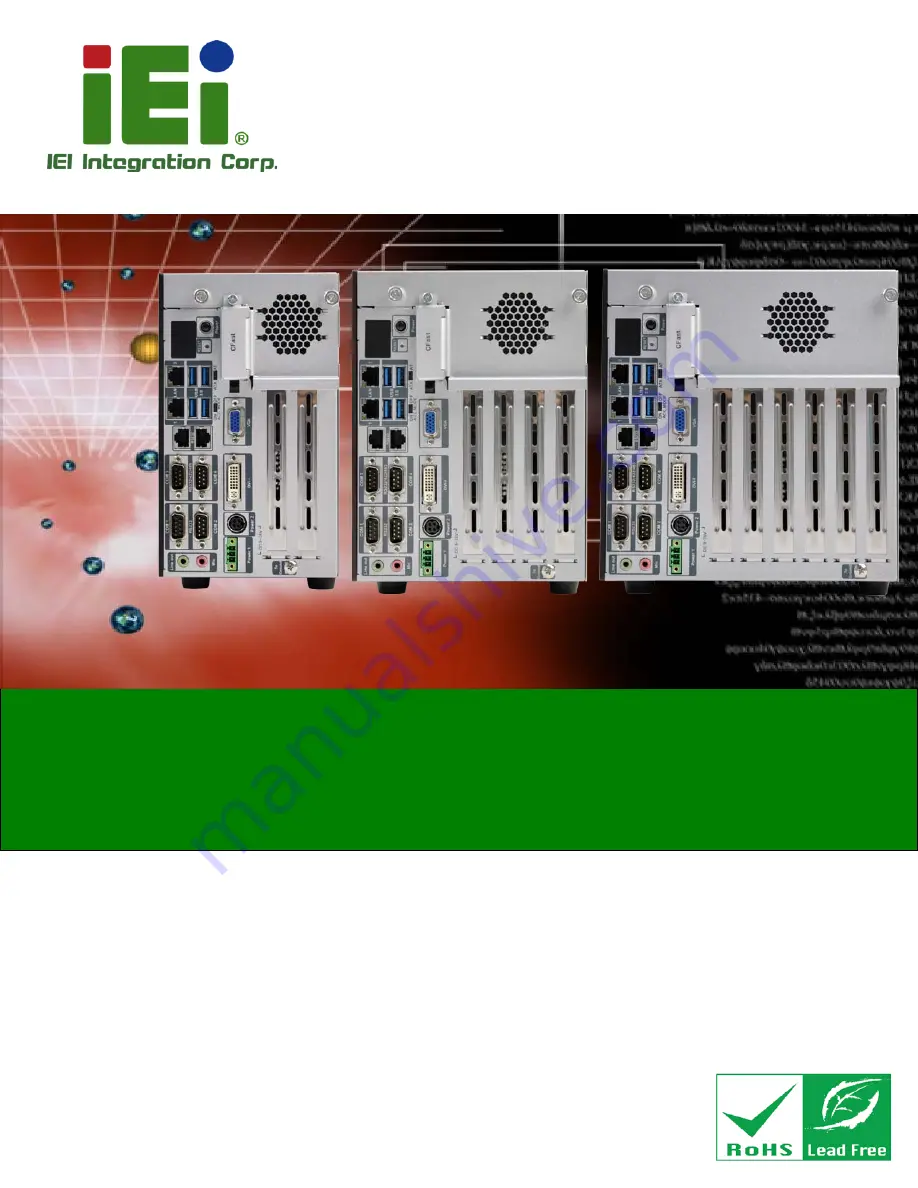
TANK-860-HM86  S e rie s  


Em b e d d e d   S ys te m   with   4th  Ge n e ra tio n   In te l®  Co re ™  p ro c e s s o r,   

VGA, DVI-I, Dis p la yP o rt, Two  Gig a b it Eth e rn e t,   

Fo u r US B 3.0, Two  US B 2.0, RS -232/422/485,   

Ro HS   Co m p lia n t 

Re v. 1.04 – 29 Ap ril 2015 

Summary of Contents for TANK-860-HM86 Series

Page 1: ...m Page i Us er Manual MODEL TANK 860 HM86 Series Embedded Sys tem with 4th Generation Intel Core proces s or VGA DVI I Dis playPort Two Gigabit Ethernet Four USB 3 0 Two USB 2 0 RS 232 422 485 RoHS Compliant Rev 1 04 29 April 2015 ...

Page 2: ...ion 1 4 Technical Specifications Change Operating Temperature to 20 C 60 C 26 March 2015 1 03 Update P N of system fan Add connector pinouts of backplane 12 March 2015 1 02 Update P N of Power Adapter 150W 19 December 2014 1 01 Update Section 1 8 Backplane Options 14 November 2014 1 00 Initial release ...

Page 3: ...amages arising out of the use or inability to use the product or documentation even if advised of the possibility of such damages This document contains proprietary information protected by copyright All rights are reserved No part of this manual may be reproduced by any mechanical electronic or other means in any form without prior written permission of the manufacturer TRADEMARKS All registered ...

Page 4: ...L DIMENSIONS 23 1 9 1 TANK 860 HM86 Physical Dimensions 2 slot 23 1 9 2 TANK 860 HM86 Physical Dimensions 4 slot 24 1 9 3 TANK 860 HM86 Physical Dimensions 6 slot 25 2 UNPACKING 26 2 1 ANTI STATIC PRECAUTIONS 27 2 2 UNPACKING PRECAUTIONS 27 2 3 UNPACKING CHECKLIST 28 3 INSTALLATION 31 3 1 INSTALLATION PRECAUTIONS 32 3 2 CFAST INSTALLATION 32 3 3 HARD DISK DRIVE HDD INSTALLATION 33 3 4 SYSTEM FAN I...

Page 5: ...8 2 ACC OFF Mode 50 4 SYSTEM MOTHERBOARD 51 4 1 OVERVIEW 52 4 1 1 Layout 52 4 2 INTERNAL PERIPHERAL CONNECTORS 53 4 2 1 Backplane 12V Power Connector BP_PWR1 53 4 2 2 Battery Connector BAT1 54 4 2 3 BIOS Programming Connector SPI1 54 4 2 4 CFast Card connector CFAST1 54 4 2 5 CPU Fan Connector CPU_FAN1 54 4 2 6 EC Debug Connector LPT_DB1 55 4 2 7 EC Programming Connector JSPI1 55 4 2 8 LED Connect...

Page 6: ... INTRODUCTION 64 5 1 1 Starting Setup 64 5 1 2 Using Setup 64 5 1 3 Getting Help 65 5 1 4 Unable to Reboot after Configuration Changes 65 5 1 5 BIOS Menu Bar 65 5 2 MAIN 67 5 3 ADVANCED 68 5 3 1 ACPI Settings 69 5 3 2 RTC Wake Settings 70 5 3 3 Trusted Computing 71 5 3 4 CPU Configuration 72 5 3 5 SATA Configuration 76 5 3 6 Intel R Rapid Start Technology 76 5 3 7 USB Configuration 78 5 3 8 F81866...

Page 7: ...LIANCE 106 B SAFETY PRECAUTIONS 111 B 1 SAFETY PRECAUTIONS 112 B 1 1 General Safety Precautions 112 B 1 2 Anti static Precautions 113 B 1 3 Product Disposal 114 B 2 MAINTENANCE AND CLEANING PRECAUTIONS 114 B 2 1 Maintenance and Cleaning 114 B 2 2 Cleaning Tools 115 C DIGITAL I O INTERFACE 116 C 1 INTRODUCTION 117 C 2 ASSEMBLY LANGUAGE SAMPLE 1 118 C 3 ASSEMBLY LANGUAGE SAMPLE 2 118 D HAZARDOUS MAT...

Page 8: ...s 23 Figure 1 12 4 slot TANK 860 HM86 Physical Dimensions millimeters 24 Figure 1 13 6 slot TANK 860 HM86 Physical Dimensions millimeters 25 Figure 3 1 CFast Socket 33 Figure 3 2 CFast Socket Cover 33 Figure 3 3 Unscrew the Cover 34 Figure 3 4 Remove the Cover from TANK 860 HM86 Series 34 Figure 3 5 HDD Installation 35 Figure 3 6 HDD Retention Screws 35 Figure 3 7 System Fan Installation 36 Figure...

Page 9: ...ctor 44 Figure 3 20 Serial Device Connector 45 Figure 3 21 DB 9 RS 232 422 485 Serial Port Connector 45 Figure 3 22 USB Device Connection 46 Figure 3 23 VGA Connector 47 Figure 3 24 VGA Connector 47 Figure 3 25 Power Button 48 Figure 3 26 Power Connectors 49 Figure 4 1 System Motherboard Front 52 Figure 4 2 System Motherboard Rear 52 ...

Page 10: ... Programming Connector Pinouts SPI1 54 Table 4 5 CFast Card Connector Pinouts CFAST1 54 Table 4 6 CPU Fan Connector Pinouts CPU_FAN1 54 Table 4 7 EC Debug Connector Pinouts LPT_DB1 55 Table 4 8 EC Programming Connector Pinouts JSPI1 55 Table 4 9 LED Connector Pinouts J2 55 Table 4 11 SATA 3Gb s Drive Connectors Pinouts SATA2 56 Table 4 12 SATA Power Connectors Pinouts CN2 CN3 56 Table 4 13 TPM Con...

Page 11: ...ort Connector Pinouts COM1 61 Table 4 26 RS 232 Serial Port Connector Pinouts COM2 61 Table 4 27 RS 232 422 485 Serial Port Connector Pinouts COM3_4 61 Table 4 28 RS 232 Serial Port Connectors Pinouts LANCOM1 62 Table 4 29 USB 2 0 Connectors Pinouts USB1 62 Table 4 30 VGA Connector Pinouts VGA1 62 Table 5 1 BIOS Navigation Keys 65 TANK 860 HM86 Series ...

Page 12: ......

Page 13: ...TANK 860 HM86 Embedded Sys tem Page 1 Chapter 1 1 Introduction ...

Page 14: ...ents It is powered by the 4th generation Intel Core processor uses the Intel HM86 chipset and supports two 204 pin DDR3 SDRAM SO DIMM modules up to 16 GB 4GB memory preinstalled The TANK 860 HM86 Series includes one VGA port one DVI I port one DisplayPort two GbE LAN ports four USB 3 0 ports two USB 2 0 ports four RS 232 connectors and two RS 232 422 485 connectors ...

Page 15: ...Ie expansion TANK 860 HM86i C 4G 4A R10 2 x PCIe and 2 x PCI expansion TANK 860 HM86i C 4G 6A R10 3 x PCIe and 3 x PCI expansion Table 1 1 TANK 860 HM86 Series Model Variations 1 3 Features The TANK 860 HM86 Series features are listed below Intel HM86 chipset with 4th generation Intel Core CPU Great flexibility of expansion slots 2 slot model 2 x PCIe x 16 4 slot model 2 x PCIe x 16 2 x PCI 1 x PC...

Page 16: ... Sys tem Fan Fanless Chas s is Cons truction Extruded aluminum alloys Motherboard Proces s or CPU Intel Core i5 4400E 2 7 GHz Intel Celeron 2000E 2 2 GHz Chips et Intel HM86 Sys tem Memory 2 x 204 pin DDR3 SO DIMM 4 GB pre installed system max 16 GB IPMI iRIS Solution iRIS 2400 Storage Hard Drive 2 x 2 5 SATA 6Gb s HDD SSD bay CFas t 1 x CFast mSATA 1 x mSATA SATA 3Gb s signal I O Interfaces USB 3...

Page 17: ... 802 1b g n 1T1R optional Expansions PCI PCIe 2 A Two PCIe x8 physical PCIe x16 slot 4 A Two PCIe x8 physical PCIe x16 slot 2 x PCI 6 A One PCIe x8 physical PCIe x16 slot 2 x PCIe by 4 3 x PCI PCIe Mini 1 x Full Size Co lay mSATA Reliability Mounting Wall mount Operating Temperature 20 C 60 C with air flow SSD 5 95 non condensing Operating Shock Half sine wave shock 5G 11ms 3 shocks per axis Opera...

Page 18: ...ft Windows 8 Embedded Microsoft Windows Embedded Standard 7 E Table 1 2 Technical Specifications 1 5 Front Panel 1 5 1 TANK 860 HM86 2 s lot Front Panel The front panel of the TANK 860 HM86 Series has the following features Figure 1 2 Figure 1 2 TANK 860 HM86 Series Front Panel ...

Page 19: ...6 V power input 1 x Mic in port pink 1 x Line out port green 2 x RS 232 serial ports DB 9 2 x RS 232 serial ports RJ 45 2 x RS 232 422 485 serial ports DB 9 2 x Gigabit Ethernet ports RJ 45 4 x USB 3 0 ports 1 x Reset button 6 x LED indicators Section 1 7 1 x Power button 1 x CFast 1 x VGA port 1 X DVI I port 1 x To Ground 2 x Expansion slots 1 x ACC mode switch 1 x AT ATX mode switch ...

Page 20: ...re 1 2 Figure 1 3 TANK 860 HM86 Series Front Panel Connectors and buttons on the front panel include the following 1 x 4 pin power DC jack for 9 V 36 V power input 1 x Power terminal block for 9 V 36 V power input 1 x Mic in port pink 1 x Line out port green 2 x RS 232 serial ports DB 9 2 x RS 232 serial ports RJ 45 2 x RS 232 422 485 serial ports DB 9 ...

Page 21: ...ge 9 2 x Gigabit Ethernet ports RJ 45 4 x USB 3 0 ports 1 x Reset button 6 x LED indicators Section 1 7 1 x Power button 1 x CFast 1 x VGA port 1 X DVI I port 1 x To Ground 4 x Expansion slots 1 x ACC mode switch 1 x AT ATX mode switch ...

Page 22: ...ure 1 2 Figure 1 4 TANK 860 HM86 Series Front Panel Connectors and buttons on the front panel include the following 1 x 4 pin power DC jack for 9 V 36 V power input 1 x Power terminal block for 9 V 36 V power input 1 x Mic in port pink 1 x Line out port green 2 x RS 232 serial ports DB 9 2 x RS 232 serial ports RJ 45 2 x RS 232 422 485 serial ports DB 9 ...

Page 23: ...ton 1 x CFast 1 x VGA port 1 X DVI I port 1 x To Ground 6 x Expansion slots 1 x ACC mode switch 1 x AT ATX mode switch 1 6 Rear Panel The rear panel of the TANK 860 HM86 Series has the following features Figure 1 2 Figure 1 5 TANK 860 HM86 Series Rear Panel Connectors on the front panel include the following 1 x DisplayPort connector 1 x DIO connector ...

Page 24: ... The descriptions of each LED indicator are listed below LED Indicator Des cription AT Power Mode The current power mode status is AT mode Controlled by the AT ATX power mode switch i Shows IPMI status Power LED1 Breathing Orange Standby mode Power LED2 Solid blue Power on mode HDD Shows HDD status CPU Temperature Alert BLUE CPU temperature is normal RED CPU temperature is too high Table 1 3 LED I...

Page 25: ...dded Sys tem Page 13 WARNING The CPU Temperature Alert LED turns red when the CPU temperature is too high If this situation occurs lower the environment temperature or close some running applications to cool down the CPU ...

Page 26: ...Sys tem Page 14 1 8 Backplane Options The backplane options of the TANK 860 HM86 Series are shown below Figure 1 7 HPE 2S86 for 2 slot model PWR1 Pin Description 1 GND 2 GND 3 12 V 4 12 V Figure 1 8 HPE 4S86 for 4 slot model ...

Page 27: ...TANK 860 HM86 Embedded Sys tem Page 15 PWR1 Pin Description 1 GND 2 GND 3 12 V 4 12 V USB1 Pin Description 1 VCC 2 Data 3 Data 4 GND ...

Page 28: ... C 4 GND 5 N C 6 1 5 V 7 WLAN_CLKREQ 8 N C 9 GND 10 N C 11 CLK 12 N C 13 CLK 14 N C 15 GND 16 N C 17 PCIRST 18 GND 19 N C 20 VCC3 21 GND 22 PCIRST 23 PCIE RXN 24 VCC3 25 PCIE RXP 26 GND 27 GND 28 1 5 V 29 GND 30 SMBCLK 31 PCIE TXN 32 SMBDATA 33 PCIE TXP 34 GND 35 GND 36 USBD 37 GND 38 USBD 39 VCC3 40 GND ...

Page 29: ...ys tem Page 17 Pin Description Pin Description 41 VCC3 42 N C 43 GND 44 RF_LINK 45 N C 46 BLUELED 47 N C 48 1 5 V 49 N C 50 GND 51 N C 52 VCC3 Figure 1 9 HPE 6S86 for 6 slot model PWR1 Pin Description 1 GND 2 GND 3 12 V 4 12 V ...

Page 30: ...NK 860 HM86 Embedded Sys tem Page 18 USB1 Pin Description 1 VCC 2 Data 3 Data 4 GND MINI PCIE1 Pin Description Pin Description 1 PCIE_WAKE 2 VCC3 3 N C 4 GND 5 N C 6 1 5 V 7 WLAN_CLKREQ 8 N C 9 GND 10 N C ...

Page 31: ...MBCLK 31 PCIE TXN 32 SMBDATA 33 PCIE TXP 34 GND 35 GND 36 USBD 37 GND 38 USBD 39 VCC3 40 GND 41 VCC3 42 N C 43 GND 44 RF_LINK 45 N C 46 BLUELED 47 N C 48 1 5 V 49 N C 50 GND 51 N C 52 VCC3 The supported signals of the backplane slots are listed below Backplane Slot Signal 2 s lot model PCIe x16 PCIe x8 PCIe x16 PCIe x8 4 s lot model PCIe x16 PCIe x8 PCIe x16 PCIe x8 PCI PCI PCI PCI 6 slot model PC...

Page 32: ...V adaptor backplane total power limit 30W Rated Voltage Rated Current 5 V 4 0 A 12 V 2 5 A 12 V 0 1 A 3 3 V 5 0 A Table 1 5 Rated Voltage and Current 150W 12V adaptor backplane total power limit 50W Rated Voltage Rated Current 5 V 4 0 A 12 V 4 0A 12 V 0 1 A 3 3 V 5 0 A Table 1 6 Rated Voltage and Current 180W 19V adaptor backplane total power limit 70W Rated Voltage Rated Current 5 V 4 0 A 12 V 5 ...

Page 33: ...ter 3 Please check your add on card total consumption to choose suitable power adapter NOTE When using an expansion card with high power consumption it is recommended to install an external power supply to the 12V power input connector on the backplane The three types of backplane support standard PCI PCIe cards with maximum dimensions WxL 110 x 230 mm The figure below shows how to connect an exte...

Page 34: ...TANK 860 HM86 Embedded Sys tem Page 22 Figure 1 10 Backplane Power ...

Page 35: ...g sections describe the physical dimensions for each model of the TANK 860 HM86 Series 1 9 1 TANK 860 HM86 Phys ical Dimens ions 2 s lot The physical dimensions of the 2 slot TANK 860 HM86 are shown in Figure 1 10 Figure 1 11 2 slot TANK 860 HM86 Physical Dimensions millimeters ...

Page 36: ...Embedded Sys tem Page 24 1 9 2 TANK 860 HM86 Phys ical Dimens ions 4 s lot The physical dimensions of the 4 slot TANK 860 HM86 are shown in Figure 1 12 Figure 1 12 4 slot TANK 860 HM86 Physical Dimensions millimeters ...

Page 37: ...Embedded Sys tem Page 25 1 9 3 TANK 860 HM86 Phys ical Dimens ions 6 s lot The physical dimensions of the 6 slot TANK 860 HM86 are shown in Figure 1 13 Figure 1 13 6 slot TANK 860 HM86 Physical Dimensions millimeters ...

Page 38: ...TANK 860 HM86 Embedded Sys tem Page 26 Chapter 2 2 Unpacking ...

Page 39: ...wristband Wearing a simple anti static wristband can help to prevent ESD from damaging the board Self grounding Before handling the board touch any grounded conducting material During the time the board is handled frequently touch any conducting materials that are connected to the ground Use an anti static pad When configuring the TANK 860 HM86 Series place it on an antic static pad This reduces t...

Page 40: ...or vendor you purchased the TANK 860 HM86 Series from or contact an IEI sales representative directly To contact an IEI sales representative please send an email to sales ieiworld com The TANK 860 HM86 Series is shipped with the following components Quantity Item and Part Number Image Standard 1 TANK 860 HM86 Series 2 Mounting Brackets 1 One Key Recovery CD P N 7B000 000724 RS 1 User Manual and Dr...

Page 41: ...an P N 19FFD124015LB 000001 RS Power Adapter 120W P N 63000 FSP120AAB RS Power Cord EUROPEAN CODE VDE P N 32000 089900 RS AMERICA CODE UL P N 32701 000500 200 RS JAPAN CODE PSE P N 32000 106700 RS AUSTRAIAN CODE SAA P N 32704 000300 100 RS Power Adapter 150W P N 63000 FSP150AHAN1808 RS Power Cord EUROPEAN CODE VDE P N 32000 000002 RS ...

Page 42: ...DE PSE P N 32706 000100 100 RS AUSTRAIAN CODE SAA P N 32000 000022 RS Note It is suggested to use the 90 W adapter for applications without add on cards For applications with add on cards please choose an adapter based on the power consumption of the TANK 860 65 W plus that of the add on card ...

Page 43: ...TANK 860 HM86 Embedded Sys tem Page 31 Chapter 3 3 Ins tallation ...

Page 44: ... qualified personnel Maintenance upgrades or repairs may only be carried out by qualified personnel who are familiar with the associated dangers Air Circulation Make sure there is sufficient air circulation when installing the TANK 860 HM86 Series The TANK 860 HM86 Series s cooling vents must not be obstructed by any objects Blocking the vents can cause overheating of the TANK 860 HM86 Series Leav...

Page 45: ...e CFast socket cover Figure 3 2 Figure 3 2 CFast Socket Cover Step 3 Correctly align the CFast card with the socket and insert the CFast card into the socket Step 4 Reinstall the cover 3 3 Hard Dis k Drive HDD Ins tallation To install the hard drive please follow the steps below ...

Page 46: ...nd then lift the cover up gently Figure 3 3 Figure 3 3 Unscrew the Cover Step 2 Unplug the SATA signal and power cables connected to the TANK 860 HM86 Series and then put the cover on a flat surface Figure 3 4 Figure 3 4 Remove the Cover from TANK 860 HM86 Series Step 3 Attach the HDD to the HDD bracket and then slide the HDD to connect with the SATA connector Figure 3 5 ...

Page 47: ...igure 3 5 HDD Installation Step 4 Secure the HDD with the HDD bracket by four retention screws Figure 3 6 Figure 3 6 HDD Retention Screws Step 5 Reconnect the SATA signal and power cables to the TANK 860 HM86 Series Step 6 Reinstall the cover ...

Page 48: ...Figure 3 3 Step 2 Unplug the SATA signal and power cables connected to the TANK 860 HM86 Series and then place the cover on a flat surface Figure 3 4 Step 3 Attach the system fan to the TANK 860 HM86 Series and secure it by four retention screws Figure 3 7 Figure 3 7 System Fan Installation Step 4 Connect the system fan cable to the CPU_FAN connector on the motherboard of TANK 860 HM86 Series Step...

Page 49: ... 8 Left Side Panel Figure 3 8 Mounting Bracket Retention Screws Step 3 Secure the brackets to the system by inserting two retention screws into each bracket Figure 3 8 Step 4 Drill holes in the intended installation surface Step 5 Align the mounting holes in the sides of the mounting brackets with the predrilled holes in the mounting surface Step 6 Insert four retention screws two in each bracket ...

Page 50: ...r terminal block Reset button RS 232 RS 232 422 485 USB VGA 3 6 1 ACC Mode Selection The ACC mode is designed for vehicle applications The TANK 860 HM86 Series allows turning the ACC mode on or off The setting can be made through the ACC mode switch on the external peripheral interface panel as shown below Figure 3 9 ACC Mode Switch ...

Page 51: ...mode switch on the external peripheral interface panel as shown below Figure 3 10 AT ATX Power Mode Switch 3 6 3 Audio Connector The audio jacks connect to external audio devices Line Out port Green Connects to a headphone or a speaker With multi channel configurations this port can also connect to front speakers Microphone Pink Connects a microphone Figure 3 11 Audio Connector ...

Page 52: ...female DVI I connector on the front panel The DVI connectors are connected to digital display devices To connect a digital display device to the TANK 860 HM86 Series please follow the instructions below Step 1 Locate the DVI connector The location of the DVI connector is shown in Chapter 1 Step 2 Align the DVI connector Align the male DVI connector on the digital display device cable with the fema...

Page 53: ...ning the two retention screws on either side of the connector 3 6 7 LAN Connectors The LAN connectors allow connection to an external network Step 1 Locate the RJ 45 connectors The locations of the RJ 45 connectors are shown in Figure 1 2 Step 2 Align the connectors Align the RJ 45 connector on the LAN cable with one of the RJ 45 connectors on the TANK 860 HM86 Series See Figure 3 14 ...

Page 54: ...rnet Connector The RJ 45 Ethernet connector has two status LEDs one green and one yellow The green LED indicates activity on the port and the yellow LED indicates the port is linked See Table 3 1 Activity Link LED Speed LED STATUS DESCRIPTION STATUS DESCRIPTION Off No link Off 10 Mbps connection Yellow Linked Green 100 Mbps connection Blinking TX RX activity Orange 1 Gbps connection Table 3 1 RJ 4...

Page 55: ...IN Connector The power connector connects to the 9 V 36 V DC power adapter Figure 3 17 Power Input Connector 3 6 10 RJ 45 RS 232 Serial Ports RS 232 serial port devices can be attached to the RJ 45 RS 232 serial ports on the rear panel Step 1 Locate the RJ 45 RS 232 connectors The locations of the RJ 45 RS 232 connectors are shown in Figure 1 2 Step 2 Insert the RJ 45 connector Insert the RJ 45 co...

Page 56: ... Secure the connector Secure the serial device connector to the external interface by tightening the two retention screws on either side of the connector Figure 3 19 RJ 45 RS 232 Serial Port Connector 3 6 11 DB 9 RS 232 422 485 Serial Port Connectors DB 9 RS 232 422 485 serial port devices can be attached to the DB 9 ports on the rear panel Step 1 Locate the DB 9 connector The locations of the DB ...

Page 57: ... Device Connector Step 3 Secure the connector Secure the serial device connector to the external interface by tightening the two retention screws on either side of the connector Figure 3 21 DB 9 RS 232 422 485 Serial Port Connector 3 6 12 USB Connectors The USB ports are for connecting USB peripheral devices to the system Step 1 Locate the USB connectors The locations of the USB connectors are sho...

Page 58: ...A connector connects to a monitor that accepts VGA video input Step 1 Locate the female DB 15 connector The location of the female DB 15 connector is shown in Figure 1 2 Step 2 Align the VGA connector Align the male DB 15 connector on the VGA screen cable with the female DB 15 connector on the external peripheral interface Step 3 Insert the VGA connector Once the connectors are properly aligned wi...

Page 59: ...nterface by tightening the two retention screws on either side of the connector Figure 3 24 VGA Connector 3 7 Powering On Off the Sys tem WARNING Make sure a power supply with the correct input voltage is being fed into the system Incorrect voltages applied to the system may cause damage to the internal electronic components and may also cause injury to the user ...

Page 60: ... 6 seconds Figure 3 25 Power Button 3 8 Power There are two power connectors on the rear panel Power 1 connector is a 3 pin terminal block that supports ACC On signal Power 2 connector is a DIN connector that can directly connect to a power adapter The supported power input voltages are Power 1 terminal block 9 V 36 V Power 2 DC jack 9 V 36 V ...

Page 61: ...r LED Indicators Description NOTE The power LED turns off when the power cable is unplugged from the system 3 8 1 ACC ON Mode 1 The TANK 860 HM86 Series supports single power input and also can be simultaneously connected to two power sources When both power connectors are connected to power sources with 9 V 36 V power input the one with higher voltage will supply power to the TANK 860 ...

Page 62: ...r 10s 4 When Power 1 9 V and Power 2 9 V the system will soft shut down and shut down the system power after 10s 3 8 2 ACC OFF Mode 1 The TANK 860 HM86 Series supports single power input and also can be simultaneously connected to two power sources When both power connectors are connected to power sources with 9 V 36 V power input the one with higher voltage will supply power to the TANK 860 2 Whe...

Page 63: ...TANK 860 HM86 Embedded Sys tem Page 51 4 Sys tem Motherboard Chapter 4 ...

Page 64: ...and connectors of the system motherboard 4 1 1 Layout The figures below show all the connectors and jumpers of the system motherboard The Pin 1 locations of the on board connectors are also indicated in the diagram below Figure 4 1 System Motherboard Front Figure 4 2 System Motherboard Rear ...

Page 65: ... SPI1 CFast card connector CFast socket CFAST1 CPU fan connector 4 pin wafer CPU_FAN1 DDR3 SO DIMM slot DDR3 SO DIMM slot DIMM1 DIMM2 EC debug connector 20 pin FPC connector LPT_DB1 EC programming connector 6 pin wafer JSPI1 LED connector 12 pin header J2 SATA 3Gb s drive connectors 14 pin SATA connector SATA2 SATA power connectora 2 pin wafer CN2 CN3 TPM connector 20 pin header TPM1 Table 4 1 Per...

Page 66: ... CFas t Card connector CFAST1 PIN NO DESCRIPTION PIN NO DESCRIPTION S1 GND S2 SATA_TX2 S3 SATA_TX2 S4 GND S5 SATA_RX2 S6 SATA_RX2 S7 GND PC1 CFAST_EN PC2 GND PC7 GND PC13 3 3V PC14 3 3V PC15 GND PC16 GND Table 4 5 CFast Card Connector Pinouts CFAST1 4 2 5 CPU Fan Connector CPU_FAN1 PIN NO DESCRIPTION PIN NO DESCRIPTION 1 GND 2 12V 3 FANIO1 4 FANOUT1 Table 4 6 CPU Fan Connector Pinouts CPU_FAN1 PIN...

Page 67: ... Debug Connector Pinouts LPT_DB1 4 2 7 EC Programming Connector J SPI1 PIN NO DESCRIPTION PIN NO DESCRIPTION 1 SPI_VCC_EC 2 SPI_CS0 _CN_EC 3 SPI_SO0_CN_EC 4 SPI_CLK0_CN_EC 5 SPI_SI0_CN_EC 6 GND Table 4 8 EC Programming Connector Pinouts JSPI1 4 2 8 LED Connector J 2 PIN NO DESCRIPTION PIN NO DESCRIPTION 1 V3 3S_LED 2 V3 3A_EC_LED 3 LRST_PD 4 LATX_LED 5 LPWRLED01 6 LPWRLED02 7 LIPMI_LED 8 LCPU_LED ...

Page 68: ...10 SATA 3Gb s Drive Connectors Pinouts SATA2 4 2 10 SATA Power Connectors CN2 CN3 4 2 11 TPM Connector TPM1 PIN NO DESCRIPTION PIN NO DESCRIPTION 1 TPMPCLK 2 GND 3 LPC_FRAME 5 BUF_PCIRST 6 5V 7 LPC_AD3 8 LPC_AD2 9 3 3V 10 LPC_AD1 11 LPC_AD0 12 GND 13 SMBCLK_RESUME 14 SMBDATA_RESUME 15 3V_DUAL 16 SERIRQ 17 GND 18 3 3V 19 LPCPD_N 20 LDRQ0 Table 4 12 TPM Connector Pinouts TPM1 PIN NO DESCRIPTION 1 5V...

Page 69: ...24 pin female DVI_I Ethernet and USB3 0 connectors RJ 45 USB 3 0 port LAN1_USB1 LAN2_USB2 Power connector 4 pin DC jack PWR1 Power connector 3 pin terminal block PWR2 RS 232 serial port connectors DB 9 COM1_2 RS 232 422 485 serial port connectors DB 9 COM3_4 RS 232 serial port connectors Dual RJ 45 LANCOM1 USB 2 0 connectors USB 2 0 port USB1 VGA connector DB 15 VGA1 Table 4 13 Rear Panel Connecto...

Page 70: ...ANE0_P 2 GND 3 DPD_OB_LANE0_N 4 DPD_OB_LANE1_P 5 GND 6 DPD_OB_LANE1_N 7 DPD_OB_LANE2_P 8 GND 9 DPD_OB_LANE2_N 10 DPD_OB_LANE3_P 11 GND 12 DPD_OB_LANE3_N 13 GND 14 GND 15 DPD_AUX_CTRL_P2 16 GND 17 DPD_AUX_CTRL_N2 18 DDI1_HPD 19 GND 20 3 3V Table 4 16 DisplayPort connector Pinouts DISPLAY_PORT1 4 3 4 DVI Connector DVI_1 PIN NO DESCRIPTION PIN NO DESCRIPTION 1 DVI_TMDS_C_DATA2 15 GND 2 DVI_TMDS_C_DAT...

Page 71: ...IN DESCRIPTION PIN DESCRIPTION 1 VCC 10 VCC 2 USB_DATA 11 USB_DATA 3 USB_DATA 12 USB_ DATA 4 GND 13 GND 5 USB3_RX 14 USB3_RX 6 USB3_RX 15 USB3_ RX 7 GND 16 GND 8 USB3_TX 17 USB3_TX 9 USB3_TX 18 USB3_TX Table 4 18 USB 3 0 Port Pinouts USB1 PIN DESCRIPTION PIN DESCRIPTION 20 LAN1_MDI0P 24 LAN1_MDI2P 21 LAN1_MDI0N 25 LAN1_MDI2N 22 LAN1_MDI1P 26 LAN1_MDI3P 23 LAN1_MDI1N 27 LAN1_MDI3N Table 4 19 LAN Pi...

Page 72: ...Port Pinouts USB2 PIN DESCRIPTION PIN DESCRIPTION 20 LAN2_MDI0P 24 LAN2_MDI2P 21 LAN2_MDI0N 25 LAN2_MDI2N 22 LAN2_MDI1P 26 LAN2_MDI3P 23 LAN2_MDI1N 27 LAN2_MDI3N Table 4 21 LAN Pinouts LAN2 4 3 7 Power Connector PWR1 PIN NO DESCRIPTION PIN NO DESCRIPTION 1 VIN 2 GND 3 VIN 4 GND 5 GND Table 4 22 Power Connector Pinouts PWR2 4 3 8 Power Connector PWR2 PIN NO DESCRIPTION PIN NO DESCRIPTION 1 ACCON 2 ...

Page 73: ...TR2 14 GND 15 NDSR2 16 NRTS2 17 NCTS2 18 NRI2 Table 4 25 RS 232 Serial Port Connector Pinouts COM2 4 3 10 RS 232 422 485 Serial Port Connector COM3_4 PIN NO DESCRIPTION PIN NO DESCRIPTION 1 NDCD3 RX 2 NRXD3 RX 3 NTXD3 TX 4 NDTR3 TX 5 GND 6 NDSR3 7 NRTS3 8 NCTS3 9 NRI3 10 NDCD4 RX 11 NRXD4 RX 12 NTXD4 TX 13 NDTR4 TX 14 GND 15 NDSR4 16 NRTS4 17 NCTS4 18 NRI4 Table 4 26 RS 232 422 485 Serial Port Con...

Page 74: ... Pinouts LANCOM1 4 3 12 USB 2 0 Connectors USB1 PIN NO DESCRIPTION PIN NO DESCRIPTION 1 5V 2 GND 3 USB20_C_N10 4 USB20_C_P11 5 USB20_C_P10 6 USB20_C_N11 7 GND 8 5V Table 4 28 USB 2 0 Connectors Pinouts USB1 4 3 13 VGA Connector VGA1 PIN NO DESCRIPTION PIN NO DESCRIPTION 1 Red 2 Green 3 Blue 4 NC 5 GND 6 GND 7 GND 8 GND 9 VGAVCC 10 HOTPLUG 11 NC 12 DDCDAT 13 HSYNC 14 VSYNC 15 DDCCLK Table 4 29 VGA ...

Page 75: ...TANK 860 HM86 Embedded Sys tem Page 63 Chapter 5 5 BIOS ...

Page 76: ...ys 1 Press the DEL or F2 key as soon as the system is turned on or 2 Press the DEL or F2 key when the Press DEL or F2 to enter SETUP message appears on the screen If the message disappears before the DEL or F2 key is pressed restart the computer and try again 5 1 2 Us ing Setup Use the arrow keys to highlight items press ENTER to select use the PageUp and PageDown keys to change entries press F1 f...

Page 77: ...IOS Navigation Keys 5 1 3 Getting Help When F1 is pressed a small help window describing the appropriate keys to use and the possible selections for the highlighted item appears To exit the Help Window press ESC or the F1 key again 5 1 4 Unable to Reboot after Configuration Changes If the computer cannot boot after changes to the system configuration is made CMOS defaults Use the jumper described ...

Page 78: ...edded Sys tem Page 66 Save Exit Selects exit options and loads default settings The following sections completely describe the configuration options found in the menu items at the top of the BIOS screen and listed above ...

Page 79: ...Hz Processor ID 306c3 Stepping C0 Number of Processors 2Core s 4Thread s Microcode Revision 12 GT Info GT2 800 MHz IGFX VBIOS Version 2178 Memory RC Version 1 6 1 2 Total Memory 4096 MB DDR3 Memory Frequency 1333 MHz PCH Information Name LynxPoint PCH SKU HM86 Stepping 05 C2 LAN PHY Revision A3 ME FW Version 9 0 13 1402 ME Firmware SKU 1 5MB SPI Clock Frequency DOFR Support Supported Read Status C...

Page 80: ...ate option to set the system date Manually enter the day month and year Sys tem Time xx xx xx Use the System Time option to set the system time Manually enter the hours minutes and seconds 5 3 Advanced Use the Advanced menu BIOS Menu 2 to configure the CPU and peripheral devices through the following sub menus WARNING Setting the wrong values in the sections below may cause the system to malfuncti...

Page 81: ... Values F3 Optimized Defaults F4 Save Exit ESC Exit Version 2 14 1219 Copyright C 2011 American Megatrends Inc BIOS Menu 2 Advanced 5 3 1 ACPI Settings The ACPI Settings menu BIOS Menu 3 configures the Advanced Configuration and Power Interface ACPI options Aptio Setup Utility Copyright C 2011 American Megatrends Inc Advanced ACPI Settings ACPI Sleep State S1 CPU Stop Clock Select ACPI sleep state...

Page 82: ...to the RAM is maintained The computer returns slower to a working state but more power is saved 5 3 2 RTC Wake Settings The RTC Wake Settings menu BIOS Menu 4 configures RTC wake event Aptio Setup Utility Copyright C 2011 American Megatrends Inc Advanced Wake system with Fixed Time Disabled Enable or disable System wake on alarm event When enabled System will wake on the date hr min sec specified ...

Page 83: ...annot generate a wake event Enabled If selected the following appears with values that can be selected Wake up every day Wake up date Wake up hour Wake up minute Wake up second After setting the alarm the computer turns itself on from a suspend state when the alarm goes off 5 3 3 Trus ted Computing Use the Trusted Computing menu BIOS Menu 5 to configure settings related to the Trusted Computing Gr...

Page 84: ...reen Select Item EnterSelect Change Opt F1 General Help F2 Previous Values F3 Optimized Defaults F4 Save Exit ESC Exit Version 2 14 1219 Copyright C 2011 American Megatrends Inc BIOS Menu 5 Trusted Computing Security Device Support Dis able Use the Security Device Support option to configure support for the security device Disable DEFAULT Security device support is disabled Enable Security device ...

Page 85: ... Enabled Active Processor Cores All Intel Virtualization Technology Disabled EIST Enabled Intel TXT LT Support Disabled Select Screen Select Item EnterSelect Change Opt F1 General Help F2 Previous Values F3 Optimized Defaults F4 Save Exit ESC Exit Version 2 14 1219 Copyright C 2011 American Megatrends Inc BIOS Menu 6 CPU Configuration The CPU Configuration menu BIOS Menu 6 lists the following CPU ...

Page 86: ...CPU L1 Data Cache Lists the amount of data storage space on the L1 cache L1 Code Cache Lists the amount of code storage space on the L1 cache L2 Cache Lists the amount of storage space on the L2 cache L3 Cache Lists the amount of storage space on the L3 cache Hyper threading Enabled Use the Hyper threading BIOS option to enable or disable the Intel Hyper Threading Technology Disabled Disables the ...

Page 87: ...T Disables Intel Virtualization Technology Enabled Enables Intel Virtualization Technology EIST Enabled Use the EIST option to enable or disable the Intel Speed Step Technology Disabled Disables the Intel Speed Step Technology Enabled DEFAULT Enables the Intel Speed Step Technology Intel TXT LT Support Dis abled Use the Intel TXT LT Support option to enable or disable the Intel Trusted Execution T...

Page 88: ... Values F3 Optimized Defaults F4 Save Exit ESC Exit Version 2 14 1219 Copyright C 2011 American Megatrends Inc BIOS Menu 7 SATA Configuration SATA Controller s Enabled Use the SATA Controller s option to configure the serial ATA controller Enabled DEFAULT Enables the on board SATA controller Disabled Disables the on board SATA controller SATA Mode Selection IDE Use the SATA Selection Mode option t...

Page 89: ... Help F2 Previous Values F3 Optimized Defaults F4 Save Exit ESC Exit Version 2 14 1219 Copyright C 2011 American Megatrends Inc BIOS Menu 8 Intel R Rapid Start Technology Intel R Rapid Start Technology Dis abled Use Intel R Rapid Start Technology option to configure Intel Rapid Start Technology function Disabled DEFAULT Intel Rapid Start Technology is disabled Enabled Intel Rapid Start Technology ...

Page 90: ...neral Help F2 Previous Values F3 Optimized Defaults F4 Save Exit ESC Exit Version 2 14 1219 Copyright C 2011 American Megatrends Inc BIOS Menu 9 USB Configuration USB Devices The USB Devices field lists the USB devices that are enabled on the system Legacy USB Support Enabled Use the Legacy USB Support BIOS option to enable USB mouse and USB keyboard support Normally if this option is not enabled ...

Page 91: ...1 American Megatrends Inc Advanced F81866 Super IO Configuration F81866 Super IO Chip F81866 Serial Port 1 Configuration Serial Port 2 Configuration Serial Port 3 Configuration Serial Port 4 Configuration Serial Port 5 Configuration Serial Port 6 Configuration Set Parameters of Serial Port 1 COMA Select Screen Select Item EnterSelect Change Opt F1 General Help F2 Previous Values F3 Optimized Defau...

Page 92: ...alues F3 Optimized Defaults F4 Save Exit ESC Exit Version 2 14 1219 Copyright C 2011 American Megatrends Inc BIOS Menu 11 Serial Port n Configuration Menu 5 3 8 1 1 Serial Port 1 Configuration Serial Port Enabled Use the Serial Port option to enable or disable the serial port Disabled Disable the serial port Enabled DEFAULT Enable the serial port Change Settings Auto Use the Change Settings option...

Page 93: ...Settings Auto Use the Change Settings option to change the serial port IO port address and interrupt address Auto DEFAULT The serial port IO port address and interrupt address are automatically detected IO 2F8h IRQ 3 Serial Port I O port address is 2F8h and the interrupt address is IRQ3 IO 3F8h IRQ 3 4 Serial Port I O port address is 3F8h and the interrupt address is IRQ3 4 IO 2F8h IRQ 3 4 Serial ...

Page 94: ...8h IRQ 10 11 Serial Port I O port address is 3E8h and the interrupt address is IRQ10 11 IO 2E8h IRQ 10 11 Serial Port I O port address is 2E8h and the interrupt address is IRQ10 11 Device Mode RS232 Use the Device Mode option to select the serial port mode RS232 DEFAULT Enables serial port RS 232 support RS422 Enables serial port RS 422 support RS485 Enables serial port RS 485 support 5 3 8 1 4 Se...

Page 95: ...s IRQ10 11 IO 2E8h IRQ 10 11 Serial Port I O port address is 2E8h and the interrupt address is IRQ10 11 Device Mode RS232 Use the Device Mode option to select the serial port mode RS232 DEFAULT Enables serial port RS 232 support RS422 Enables serial port RS 422 support RS485 Enables serial port RS 485 support 5 3 8 1 5 Serial Port 5 Configuration Serial Port Enabled Use the Serial Port option to e...

Page 96: ...ion Serial Port Enabled Use the Serial Port option to enable or disable the serial port Disabled Disable the serial port Enabled DEFAULT Enable the serial port Change Settings Auto Use the Change Settings option to change the serial port IO port address and interrupt address Auto DEFAULT The serial port IO port address and interrupt address are automatically detected IO 2D8h IRQ 10 Serial Port I O...

Page 97: ...elect Screen Select Item EnterSelect Change Opt F1 General Help F2 Previous Values F3 Optimized Defaults F4 Save Exit ESC Exit Version 2 14 1219 Copyright C 2011 American Megatrends Inc BIOS Menu 12 F81866 H W Monitor PC Health Status The following system parameters and values are shown The system parameters that are monitored are System Temperatures o CPU Temperature o System Temperature Fan Spee...

Page 98: ... F1 General Help F2 Previous Values F3 Optimized Defaults F4 Save Exit ESC Exit Version 2 14 1219 Copyright C 2011 American Megatrends Inc BIOS Menu 13 Smart Fan Mode Configuration Smart Fan control Auto PWM Mode Use the Smart Fan control BIOS option to configure the CPU Smart Fan Full Mode Fan is on all the time Manual PWM Mode The fan spins at the speed set in the manual setting Auto PWM Mode DE...

Page 99: ...temperature range is specified below Minimum Value 0 C Maximum Value 127 C Temperature of Start 80 WARNING Setting this value too high may cause the fan to rotate at full speed only when the CPU is at a very high temperature and therefore cause the system to be damaged The Temperature of Start option can only be set if the Smart Fan control option is set to Auto PWM Mode Use the Temperature of Sta...

Page 100: ...uty Cycle 4 PWM The Slope Duty Cycle option can only be set if the Smart Fan control option is set to Auto PWM Mode Use the Slope Duty Cycle option to select the linear rate at which the PWM mode increases with respect to an increase in temperature A list of available options is shown below 0 1 2 4 8 16 5 3 10 Serial Port Cons ole Redirection The Serial Port Console Redirection menu BIOS Menu 14 a...

Page 101: ...irection Settings COM7 Console Redirection Disabled Console Redirection Settings COM8 Console Redirection Disabled Console Redirection Settings IPMI Disabled Console Redirection Console Redirection Enable or Disable Select Screen Select Item EnterSelect Change Opt F1 General Help F2 Previous Values F3 Optimized Defaults F4 Save Exit ESC Exit Version 2 14 1219 Copyright C 2011 American Megatrends I...

Page 102: ...ds VT100 to support color function keys etc VT UTF8 Uses UTF8 encoding to map Unicode chars onto 1 or more bytes Select Screen Select Item EnterSelect Change Opt F1 General Help F2 Previous Values F3 Optimized Defaults F4 Save Exit ESC Exit Version 2 14 1219 Copyright C 2011 American Megatrends Inc BIOS Menu 15 Console Redirection Settings Terminal Type ANSI Use the Terminal Type option to specify...

Page 103: ...arity bit that can be sent with the data bits for detecting the transmission errors None DEFAULT No parity bit is sent with the data bits Even The parity bit is 0 if the number of ones in the data bits is even Odd The parity bit is 0 if the number of ones in the data bits is odd Mark The parity bit is always 1 This option does not provide error detection Space The parity bit is always 0 This optio...

Page 104: ...d recover system automatically within 10 min when OS crashes Please install Auto Recovery API service before enabling this function Select Screen Select Item EnterSelect Change Opt F1 General Help F2 Previous Values F3 Optimized Defaults F4 Save Exit ESC Exit Version 2 14 1219 Copyright C 2011 American Megatrends Inc BIOS Menu 16 iEi Feature Auto Recovery Function Dis abled Use Auto Recovery Funct...

Page 105: ... BIOS menu may cause the system to malfunction Aptio Setup Utility Copyright C 2011 American Megatrends Inc Main Advanced Chipset Boot Security Save Exit PCH IO Configuration System Agent SA Configuration PCH Parameters Select Screen Select Item EnterSelect Change Opt F1 General Help F2 Previous Values F3 Optimized Defaults F4 Save Exit ESC Exit Version 2 14 1219 Copyright C 2011 American Megatren...

Page 106: ...Exit Version 2 14 1219 Copyright C 2011 American Megatrends Inc BIOS Menu 18 PCH IO Configuration Res tore AC Power Los s Las t State Use the Restore on AC Power Loss option to specify what state the system returns to if there is a sudden loss of power to the system Power Off The system remains turned off Power On The system turns on Last State DEFAULT The system returns to its previous state If i...

Page 107: ...alues F3 Optimized Defaults F4 Save Exit ESC Exit Version 2 15 1236 Copyright C 2012 American Megatrends Inc BIOS Menu 19 PCI Express Configuration PCIe Speed Use PCIe Speed option to select the speed type of the PCIe Mini slot The following options are available Auto Default Gen1 Gen2 Detect Non Compliance Device Dis abled Use the Detect Non Compliance Device option to enable or disable the detec...

Page 108: ...y Enabled Select Screen Select Item Enter Select Change Opt F1 General Help F2 Previous Values F3 Optimized Defaults F4 Save Exit ESC Exit Version 2 15 1236 Copyright C 2012 American Megatrends Inc BIOS Menu 20 PCH Azalia Configuration Menu Azalia HD Audio Enabled Use the Azalia option to enable or disable the High Definition Audio controller Disabled The onboard High Definition Audio controller i...

Page 109: ...4 2 1 Graphics Configuration Use the Graphics Configuration BIOS Menu 22 menu to configure the video device connected to the system Aptio Setup Utility Copyright C 2012 American Megatrends Inc Chipset Graphics Configuration Primary Display Auto DVMT Pre Allocated 256M DVMT Total Gfx Mem MAX Primary IGFX Boot Display VBIOS Default Select which of IGFX PEG PCI Graphics device should be Primary Displ...

Page 110: ...ted can then only be used as graphics memory and is no longer available to applications or the operating system Configuration options are listed below 32M 64M 128M 256M Default 512M DVMT Total Gfx Mem MAX Use the DVMT Total Gfx Mem option to select DVMT5 0 total graphic memory size used by the internal graphic device The following options are available 128M 256M MAX Default Primary IGFX Boot Dis p...

Page 111: ... Select Change Opt F1 General Help F2 Previous Values F3 Optimized Defaults F4 Save Exit ESC Exit Version 2 15 1236 Copyright C 2012 American Megatrends Inc BIOS Menu 23 NB PCIe Configuration PCIEX16 Gen X Auto Use the PCIEX16 Gen X option to select the support type of the PCI Express x16 slot The following options are available Auto Default Gen1 Gen2 Gen3 Enable PEG Enabled Use the Enable PEG opt...

Page 112: ...guration Use the Memory Configuration submenu BIOS Menu 24 to view memory information Aptio Setup Utility Copyright C 2012 American Megatrends Inc Chipset Memory Information Memory Frequency 1333 Mhz Total Memory 4096 MB DDR3 DIMM1 4096 MB DDR3 DIMM2 Not Present Select Screen Select Item Enter Select Change Opt F1 General Help F2 Previous Values F3 Optimized Defaults F4 Save Exit ESC Exit Version ...

Page 113: ... Version 2 14 1219 Copyright C 2011 American Megatrends Inc BIOS Menu 25 Boot Bootup NumLock State On Use the Bootup NumLock State BIOS option to specify if the number lock setting must be modified during boot up On DEFAULT Allows the Number Lock on the keyboard to be enabled automatically when the computer system boots up This allows the immediate use of the 10 key numeric keypad located on the r...

Page 114: ...rk devices Disabled DEFAULT Ignore all PXE Option ROMs Enabled Load PXE Option ROMs Option ROM Mes s ages Force BIOS Use the Option ROM Messages option to set the Option ROM display mode Force BIOS DEFAULT Sets display mode to force BIOS Keep Current Sets display mode to current UEFI Boot Dis abled Use the UEFI Boot option to enable or disable to boot from the UEFI devices Enabled Boot from UEFI d...

Page 115: ... to boot or enter Setup In Setup the User will have Administrator rights The password length must be Minimum length 3 Maximum length 20 Administrator Password User Password Set Administrator Password Select Screen Select Item EnterSelect Change Opt F1 General Help F2 Previous Values F3 Optimized Defaults F4 Save Exit ESC Exit Version 2 14 1219 Copyright C 2011 American Megatrends Inc BIOS Menu 26 ...

Page 116: ...ct Item EnterSelect Change Opt F1 General Help F2 Previous Values F3 Optimized Defaults F4 Save Exit ESC Exit Version 2 14 1219 Copyright C 2011 American Megatrends Inc BIOS Menu 27 Exit Save Changes and Res et Use the Save Changes and Reset option to save the changes made to the BIOS options and reset the system Dis card Changes and Res et Use the Discard Changes and Reset option to exit the syst...

Page 117: ...Page 105 Save as Us er Defaults Use the Save as User Defaults option to save the changes done so far as user defaults Res tore Us er Defaults Use the Restore User Defaults option to restore the user defaults to all the setup options ...

Page 118: ...TANK 860 HM86 Embedded Sys tem Page 106 Appendix A A Regulatory Compliance ...

Page 119: ...quipment is in compliance with the essential requirements and other relevant provisions of Directive 1999 5 EC Български Bulgarian IEI Integration Corp декларира че този оборудване е в съответствие със съществените изисквания и другите приложими правила на Директива 1999 5 ЕС Česky Czech IEI Integration Corp tímto prohlašuje že tento zařízení je ve shodě se základními požadavky a dalšími příslušný...

Page 120: ... aux autres dispositions pertinentes de la directive 1999 5 CE Italiano Italian IEI Integration Corp dichiara che questo apparecchio è conforme ai requisiti essenziali ed alle altre disposizioni pertinenti stabilite dalla direttiva 1999 5 CE Latviski Latvian IEI Integration Corp deklarē ka iekārta atbilst būtiskajām prasībām un citiem ar to saistītajiem noteikumiem Direktīvas 1999 5 EK Lietuvių Li...

Page 121: ...pament este in conformitate cu cerinţele esenţiale şi cu celelalte prevederi relevante ale Directivei 1999 5 CE Slovensko Slovenian IEI Integration Corp izjavlja da je ta opreme v skladu z bistvenimi zahtevami in ostalimi relevantnimi določili direktive 1999 5 ES Slovensky Slovak IEI Integration Corp týmto vyhlasuje že zariadenia spĺňa základné požiadavky a všetky príslušné ustanovenia Smernice 19...

Page 122: ... for a Class A digital device pursuant to part 15 of the FCC Rules These limits are designed to provide reasonable protection against harmful interference when the equipment is operated in a commercial environment This equipment generates uses and can radiate radio frequency energy and if not installed and used in accordance with the instruction manual may cause harmful interference to radio commu...

Page 123: ...TANK 860 HM86 Embedded Sys tem Page 111 Appendix B B Safety Precautions ...

Page 124: ...ure the power is turned off and the power cord is disconnected when moving installing or modifying the system Do not apply voltage levels that exceed the specified voltage range Doing so may cause fire and or an electrical shock Electric shocks can occur if opened while still powered on Do not drop or insert any objects into the ventilation openings If considerable amounts of dust water or fluids ...

Page 125: ...ents are handled the following anti static precautions are strictly adhered to Wear an anti static wristband Wearing a simple anti static wristband can help to prevent ESD from damaging any electrical component Self grounding Before handling any electrical component touch any grounded conducting material During the time the electrical component is handled frequently touch any conducting materials ...

Page 126: ... and electronic products carrying the mark left must be disposed of separately from normal household waste This includes monitors and electrical accessories such as signal cables or power cords When you need to dispose of your display products please follow the guidance of your local authority or ask the shop where you purchased the product The mark on electrical and electronic products only appli...

Page 127: ...e product will be explicitly mentioned in the cleaning tips Below is a list of items to use when cleaning the TANK 860 HM86 Series Cloth Although paper towels or tissues can be used a soft clean piece of cloth is recommended when cleaning the TANK 860 HM86 Series Water or rubbing alcohol A cloth moistened with water or rubbing alcohol can be used to clean the TANK 860 HM86 Series Using solvents Th...

Page 128: ...TANK 860 HM86 Embedded Sys tem Page 116 Appendix C C Digital I O Interface ...

Page 129: ...nputs and digital outputs are generally control signals that control the on off circuit of external devices or TTL devices Data can be read or written to the selected address to enable the DIO functions NOTE For further information please refer to the datasheet for the Super I O chipset The BIOS interrupt call INT 15H controls the digital I O INT 15H AH 6FH AL 8 Set the digital port as INPUT Sub f...

Page 130: ...setting the digital port as input INT 15H AL low byte value AH 6FH AL 9 Set the digital port as OUTPUT Sub function BL Digital I O input value C 3 As s embly Language Sample 2 MOV AX 6F09H setting the digital port as output MOV BL 09H digital value is 09H INT 15H Digital Output is 1001b ...

Page 131: ...TANK 860 HM86 Embedded Sys tem Page 119 Appendix D D Hazardous Materials Dis clos ure ...

Page 132: ...es the presences of small quantities of certain materials in the product and is applicable to China RoHS only A label will be placed on each product to indicate the estimated Environmentally Friendly Use Period EFUP This is an estimate of the number of years that these substances would not leak out or undergo abrupt change This product may contain replaceable sub assemblies components which have a...

Page 133: ...cuit Board O O O O O O Metal Fas teners O O O O O O Cable As s embly O O O O O O Fan As s embly O O O O O O Power Supply As s emblies O O O O O O Battery O O O O O O O This toxic or hazardous substance is contained in all of the homogeneous materials for the part is below the limit requirement in SJ T11363 2006 X This toxic or hazardous substance is contained in at least one of the homogeneous mat...

Page 134: ...产品可能包含有较短的环境友好使用期限的可替换元件 像是电池或灯管 这些元 件将会单独标示出来 部件名称 有毒有害物质或元素 铅 Pb 汞 Hg 镉 Cd 六价铬 CR VI 多溴联苯 PBB 多溴二苯 醚 PBDE 壳体 O O O O O O 显示 O O O O O O 印刷电路板 O O O O O O 金属螺帽 O O O O O O 电缆组装 O O O O O O 风扇组装 O O O O O O 电力供应组装 O O O O O O 电池 O O O O O O O 表示该有毒有害物质在该部件所有物质材料中的含量均在 SJ T11363 2006 标准规定的限量要求以下 X 表示该有毒有害物质至少在该部件的某一均质材料中的含量超出 SJ T11363 2006 标准规定的限量要求 ...

Reviews: